PCbee - Bee Shaped PCB - solar LED light
by QC
Posted on Mon, March 27, 2023 - 02:29:10 PM
Motivation
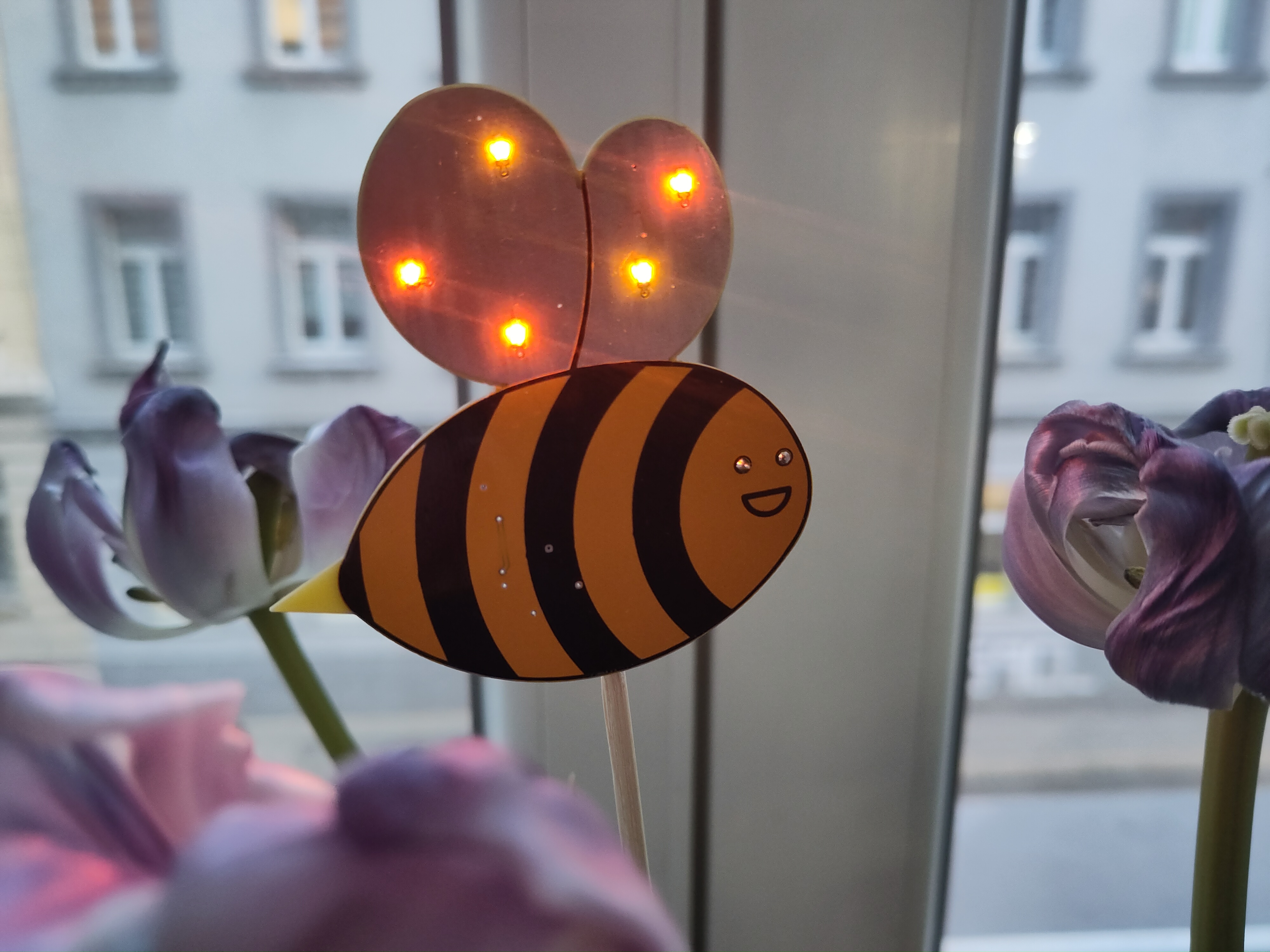
Spring weather wakes up my desire to combine stuff I tend to enjoy. As for the plant sitting on the window sill, they grow and start blooming once the first warmer days appear and that's when I thought I should design something pleasing to the eye.
Glamor shot of the final product around tulips.
Schematics
The circuit is quite straight forwardly built around the QX5252 solar controller. It uses two brand name solar cells which provide the necessary charging current for a 1.2V 40mAh NIMh battery. The cell should be fully charged within 2h of full brightness sun, but probably takes a bit longer due to the non-ideal position indoors.
After the voltage of the solar cell has fallen below 0.3·Vbatt, the controller starts the built in step-up converter feeding the blinking LEDs. Each LED has a separate resistor to be able to use different colors and mix blinking and non-blinking LEDs. With the default configuration, the battery should last for a bit more than 2.5h, practically I've seen it running for 2h on my windows sill.
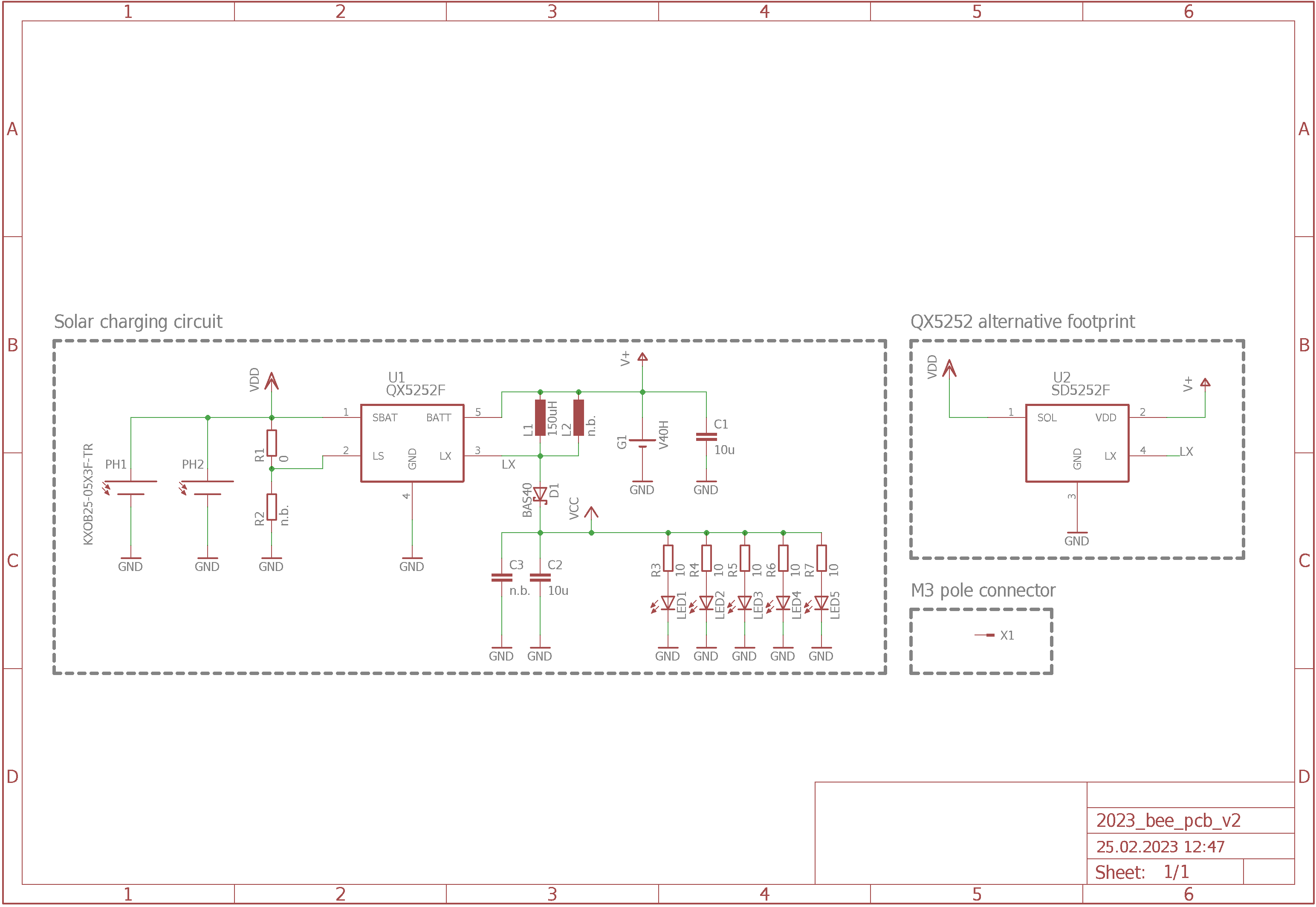 Schematics v2 for the PCbee
PCB
The PCB was a lot of tedious work to get it to the shape of a bee. I'm an engineer, artsy stuff without a technical drawing and dimensions makes me uneasy. Luckily my pretty lady helped me there and together we found a contour that fits. The PCB uses a lot of layer trickery, with exposed copper, silkscreen color, solder mask color, polygon stop and strategically placed mounting holes.
On the bottom there is an unreasonably expensive M3 threaded pole connector. It can be used with sharpened bamboo sticks or just any other M3 screw or rod. Feel free to post your mounting positions, I'm curious to find out.
Due to the prototypiness, there are a bunch of additional footprints, to add extra capacitors, inductors or different controller footprints. It can even be used with an external LDR to adapt the light levels used to switch on the LEDs.
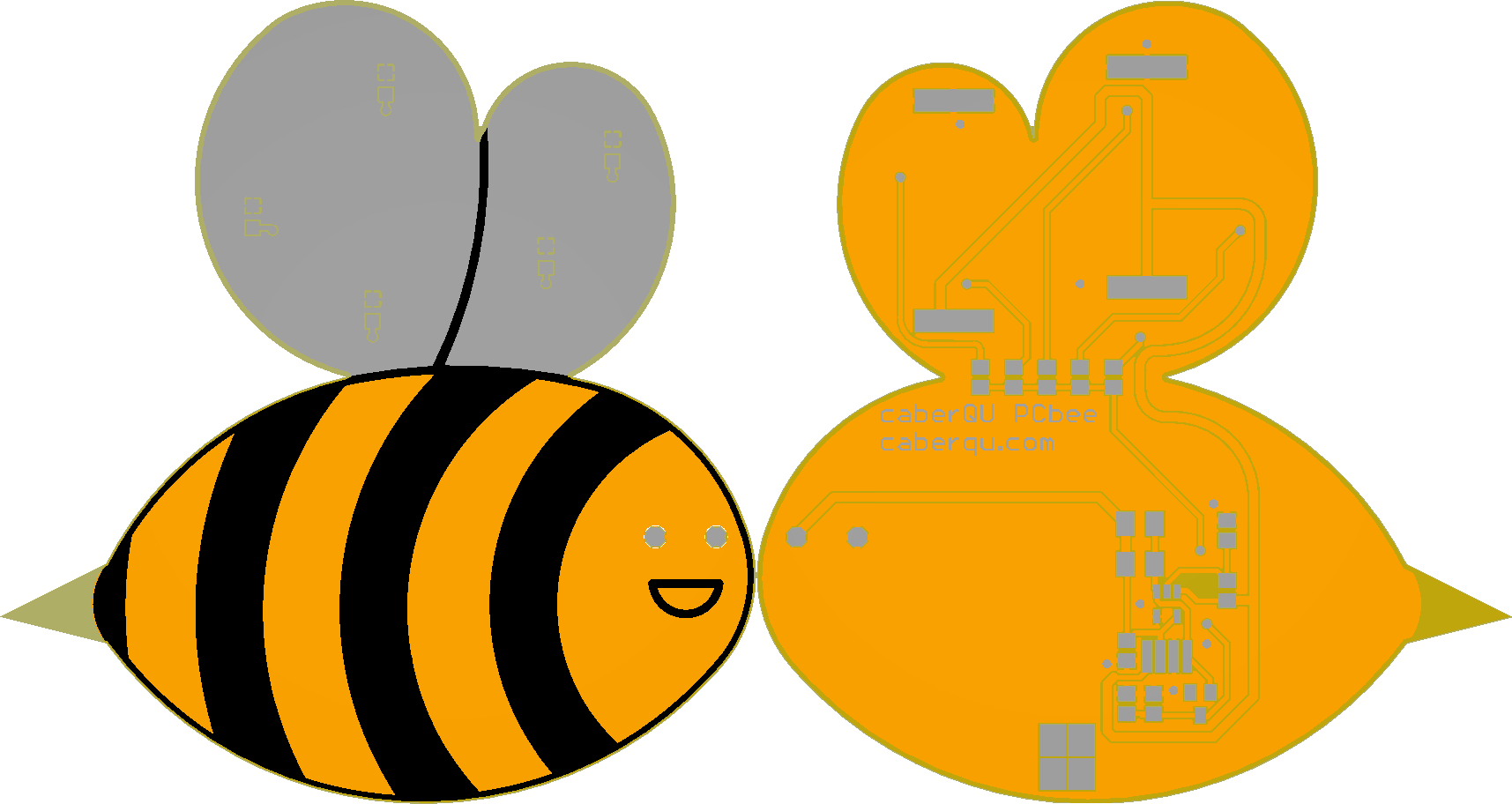 PCB screenshot top and bottom.
Conclusion
Obviously there needs to be a video, so you can also enjoy the view. The project itself is really interesting and in my opinion looks quite pleasing. The parts used turned out to be surprisingly expensive though. The PCB has to be manufactured at a special place due to the uncommon specs, the parts are unusual and hard to get and the solar cells only available from one supplier. This makes it a nice gift for someone really into electronics and not so much of a mass manufactured item.So that's that, I hope this guide didn't get too long. All the files are on github so you can download them and browse through. If you have any questions or feedback just write a message or leave a comment <3 Read More
USB midi controller
by QC
Posted on Wed, December 29, 2021 - 12:57:57 PM
Motivation
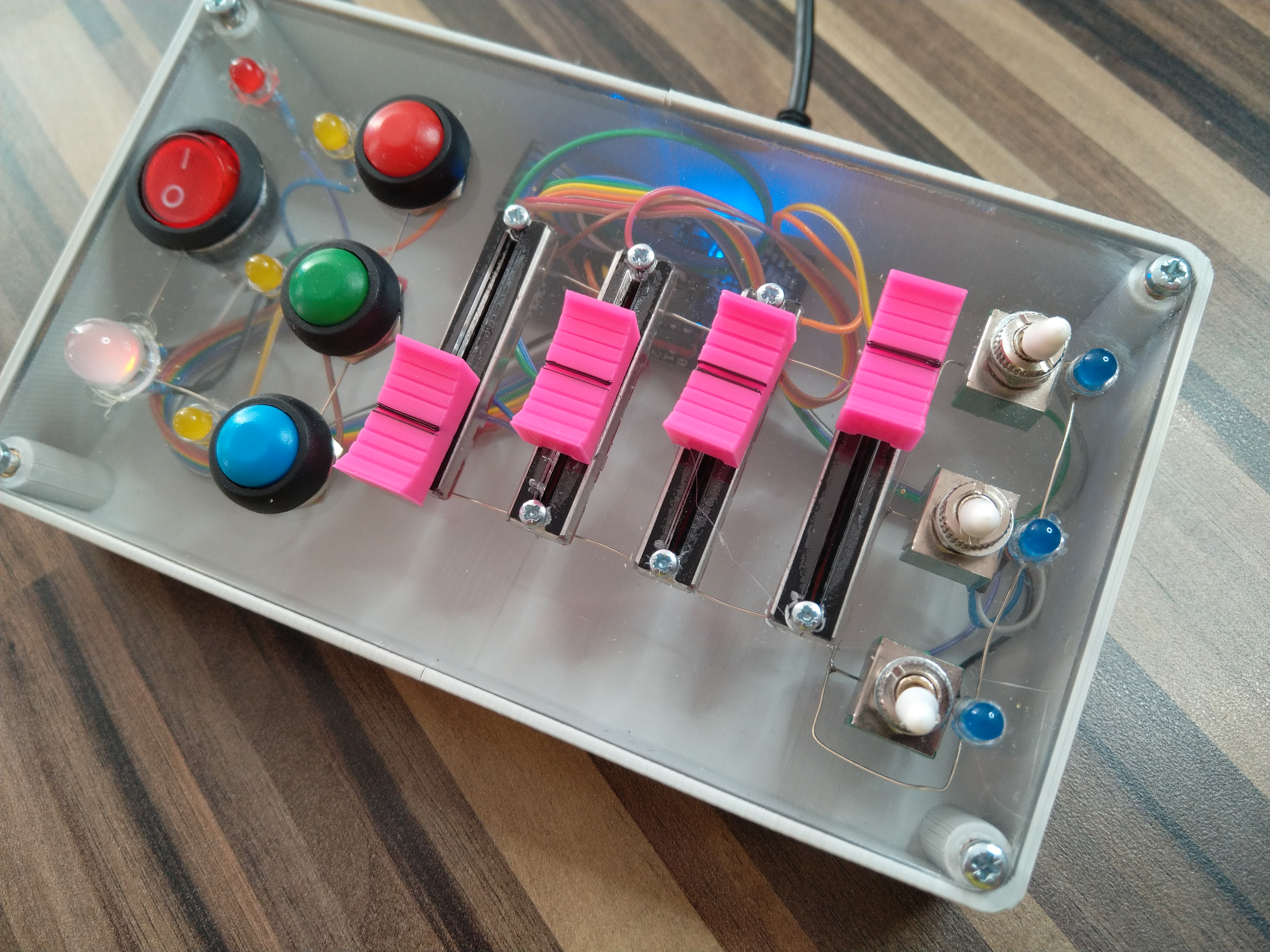
I have been browsing the net for an easy to use USB Midi controller which can be used with my mixing software Mixxx to be able to mix podcasts on the go. Initially I wanted to buy an off the shelf product from Korg, the Nanokontrol 2, but they raised their prices to 69€. That's honestly not a lot for a product this powerful, but what if I tell you that I can make it at home for less? Let's say 54€ less? Yes, I paid 15€ for the stuff (without the Arduino clone i already had). All the files are open source and uploaded to a github repository.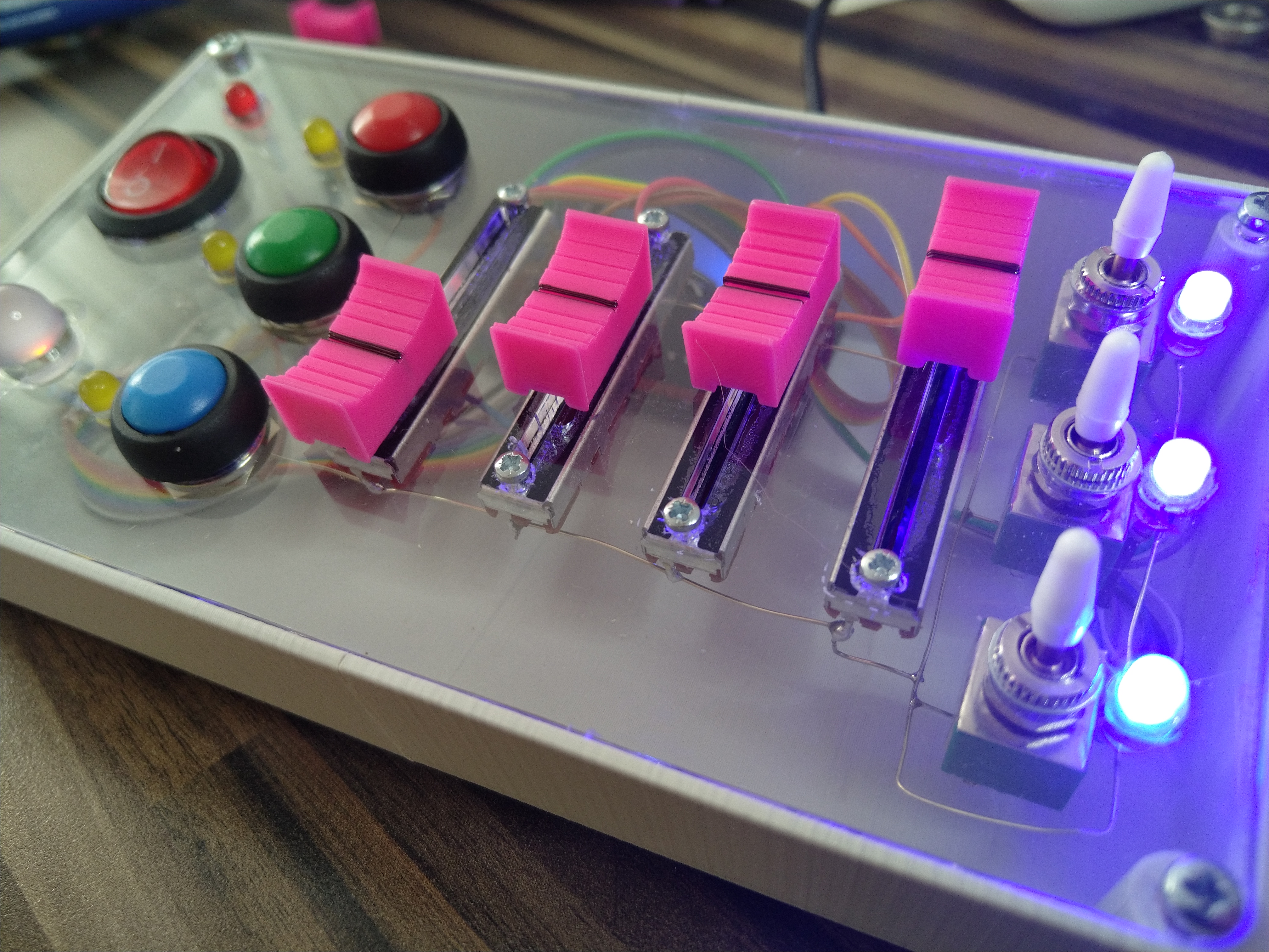 Finished fader.
Specifications
The has a few interesting features, mainly that it can easily be programmed in the Arduino IDE. The LEDs are all separately addressable, which makes them writeable via the computer interface. All switches including the big red one are also connected to the Breadboard Arduino clone. It doesn't need an external power supply or anything else.- 4x 30mm Slider Potentiometers with custom knobs.
- 7x individually addressable LEDs
- 1x red/green dual color 10mm LED for RX/TX
- 1x main switch, software controlled.
- 3x buttons
- 3x DPST switches
- micro USB to serial connection.
Hardware
The hardware was partly lasercut, and partly 3D printed. The lasercutter is a cheap chinese 40W one with a pair of really expensive thorlabs safety goggles. I used 4mm acrylic glas and grey PLA filament. The fader knobs are pink PLA.In total the stuff cost me around 15€, including the Arduino clone it would be around 33€.
| Name | Pcs | Price | Total | URL |
|---|---|---|---|---|
| Switch DPST | 4 | 1.29 | 5.16 | https://www.conrad.at/de/p/tru-components-kippschalter-250-v-ac-2-a-2-x-ein-ein-rastend-1-st-2304637.html |
| Switch red | 1 | 3.3 | 3.3 | https://www.ebay.at/itm/312093751996 |
| Button switch | 3 | 0.59 | 1.77 | https://www.ebay.at/itm/223587573763 |
| Slider Potentiometer | 4 | 0.89 | 3.56 | https://www.conrad.at/de/p/tru-components-f3031n-schiebe-potentiometer-10-k-mono-0-1-w-linear-1-st-1567032.html |
| LED 5mm | 7 | 0.02 | 0.14 | https://www.ebay.at/itm/124214363745 |
| LED 10mm | 1 | 1.26 | 1.26 | https://www.ebay.at/itm/323443837179 |
| Resistor 220 Ohm | 3 | 0.07 | 0.21 | https://www.ebay.at/itm/372813822157 |
| Resistor 1k Ohm | 6 | 0.07 | 0.42 | https://www.ebay.at/itm/372813822157 |
| Screw M3x20 & M3 inserts | 4 | |||
| Screw M2.5x6 | 8 | |||
| Breadboard BB UNO | 1 | 18 | 18 | https://www.tindie.com/products/petl/breadboard-arduino-uno-clone/ |
Bill of materials.
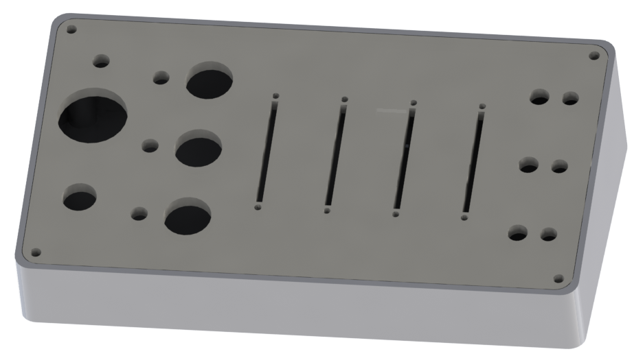 Rendering of the case and frontplate.
Frontplate:
Luckily SolidWorks can directly export to a .dxf file. This format can be read via the K40 Whisperer software and cut on the lasercutter. I avoided adding any markings on the acrylic, because it looks cleaner this way. Also I couldn't think of anything useful to add, feel free to let me know.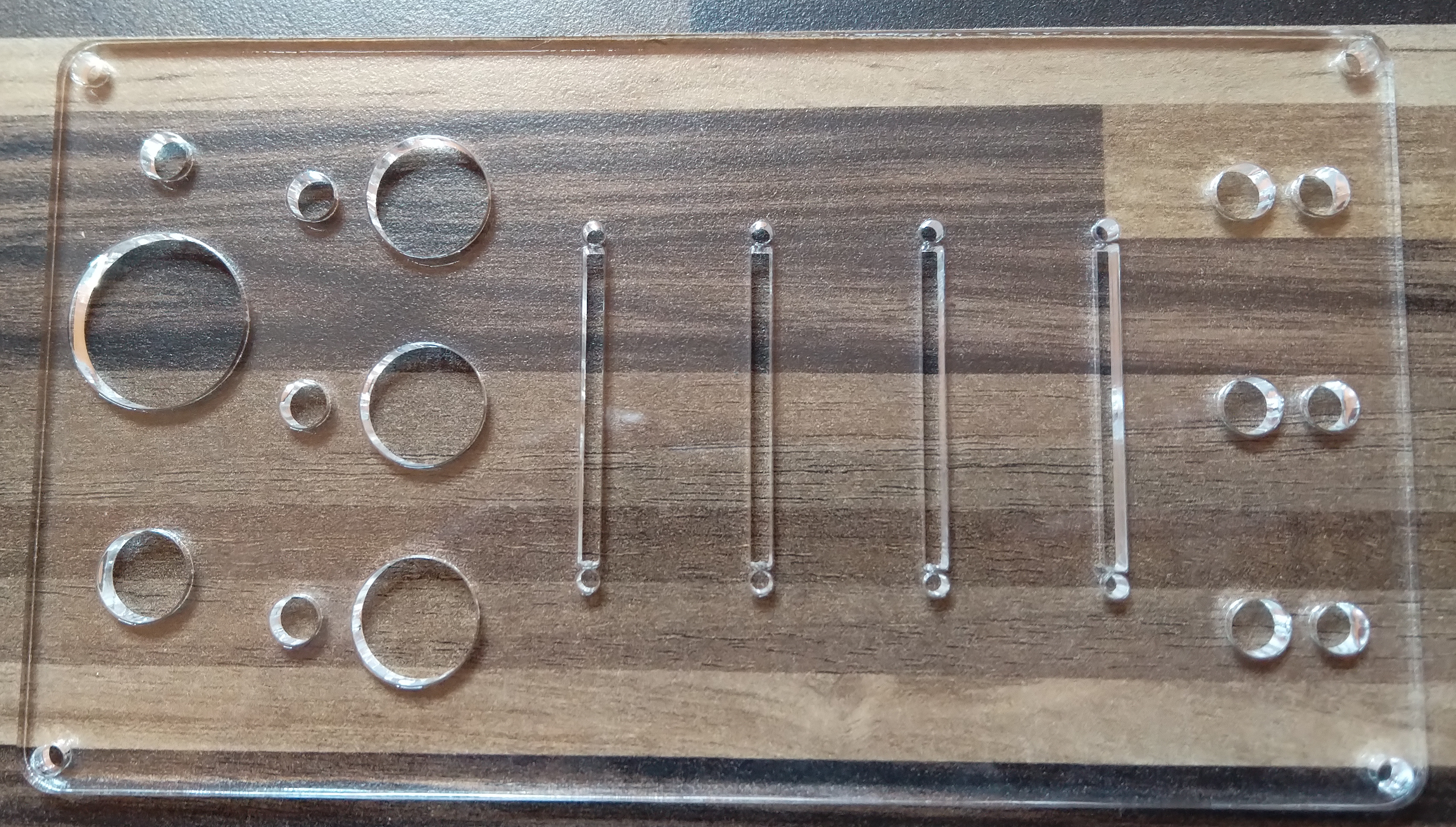 Lasercut frontplate.
Case:
I had to print the case in two parts as my 3D printer would have been too small otherwise. I glued it together with Cyanoacrylate glue, which works surprisingly well. It has four pillars for the M3 inserts, which can be put in with a soldering iron and a steady hand. The opening in the back perfectly fits the micro USB port. the print is quite easy to do for most 3D printers and should be doable with almost all materials. I used colorFabb PLA, grey for the case and pink for the sliders. The sliders have a black stripe in the middle as it looks nice. On the bottom are four 11mm diameter cutouts for 10x4mm rubber feet, this gives the case a better feeling.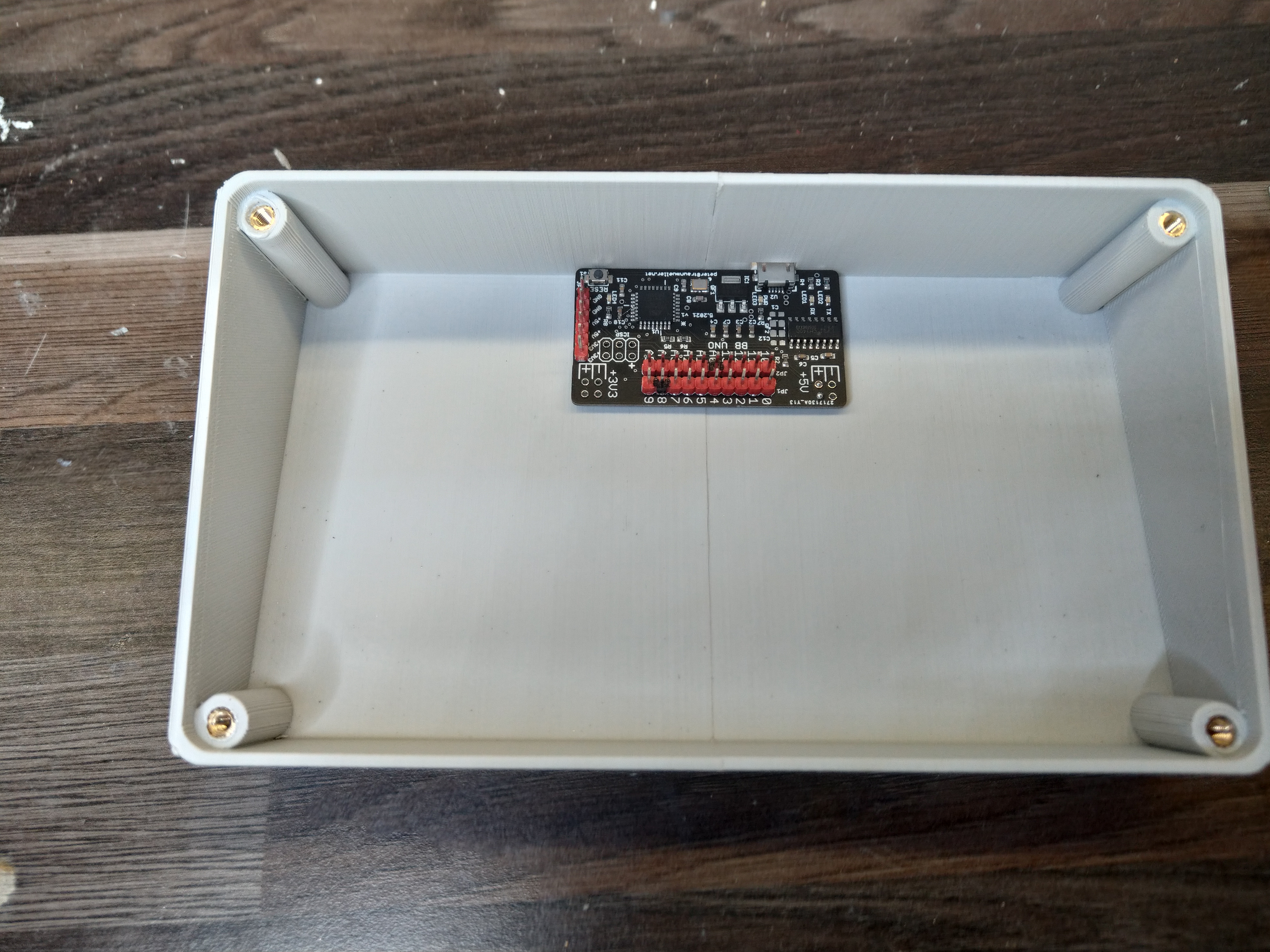 3D printed case with Arduino clone already mounted.
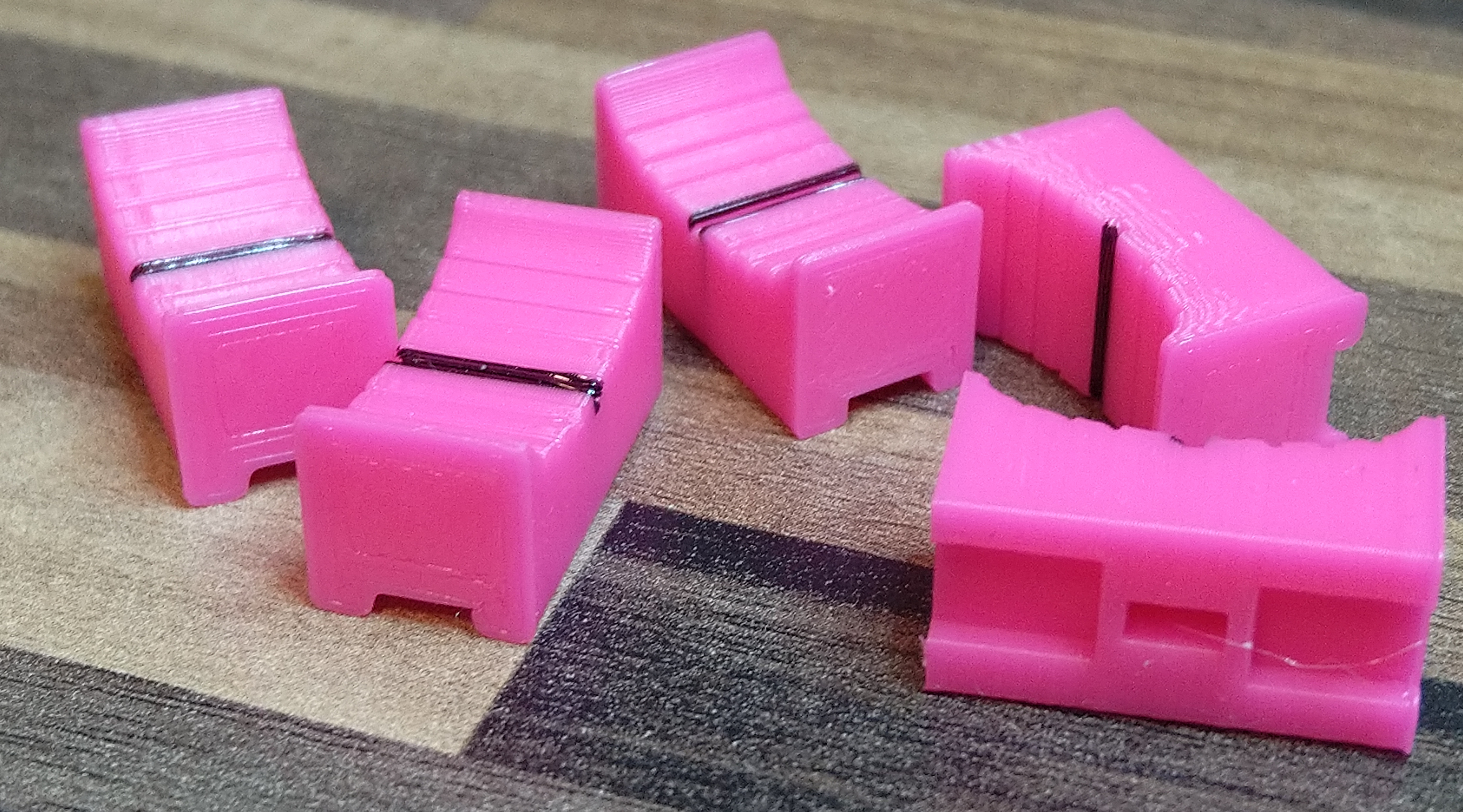 Pink sliders with black stripe.
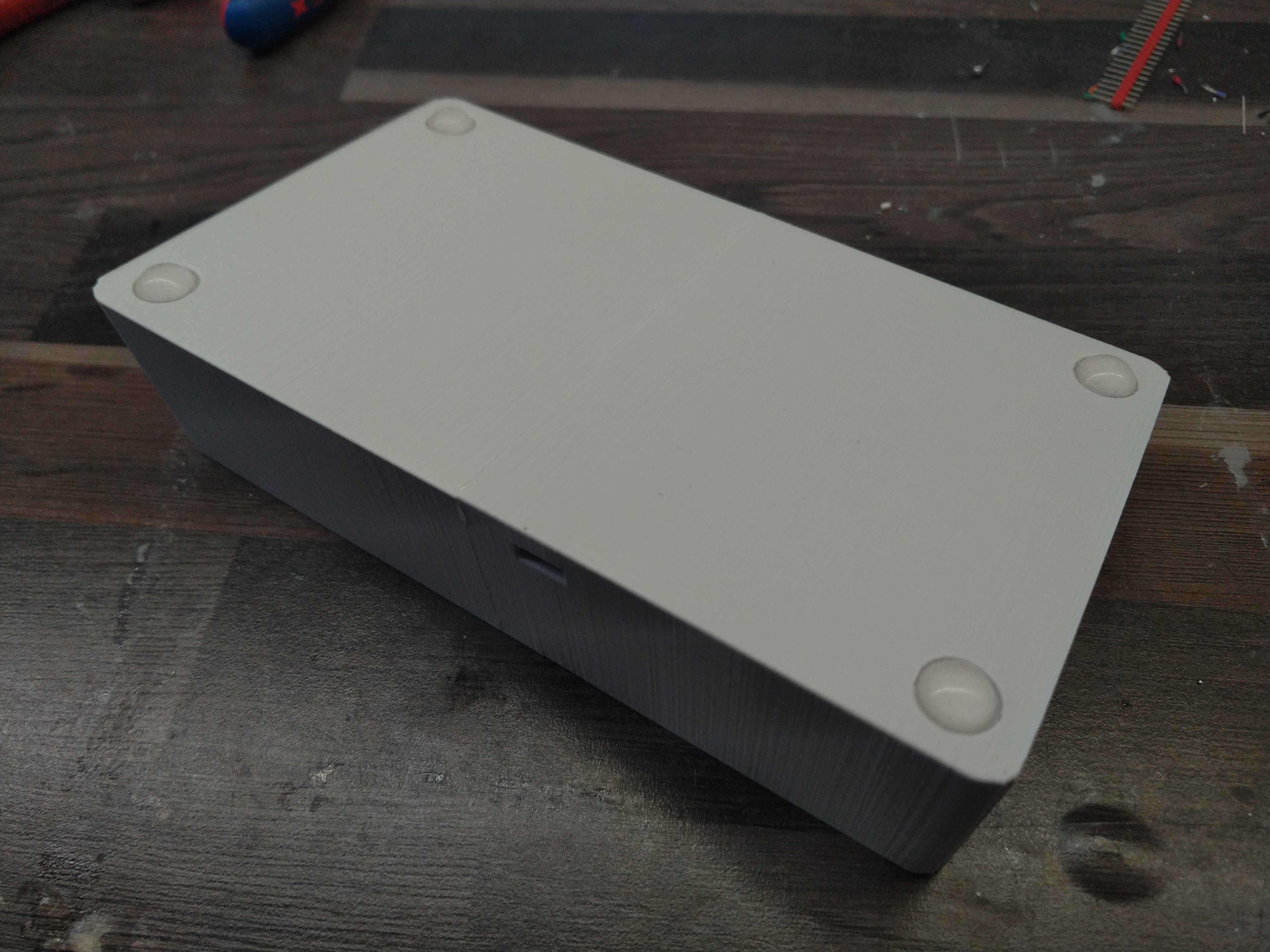 Rubber feet on the bottom of the case.
Schematics:
All of the connections were soldered directly onto the parts. The current limiting resistors are on the back of the LEDs, the blue ones got 220 Ohm due to their higher forward voltage, the others 1k Ohm. There is a ground rails going all around the back and the sliders also have +5V connected on top. The Arduino clone I had lying around was a perfect fit, as it has all IOs in two rows. Note that I had to connect a +5V wire on the back to the output row to be able to wire it up like this.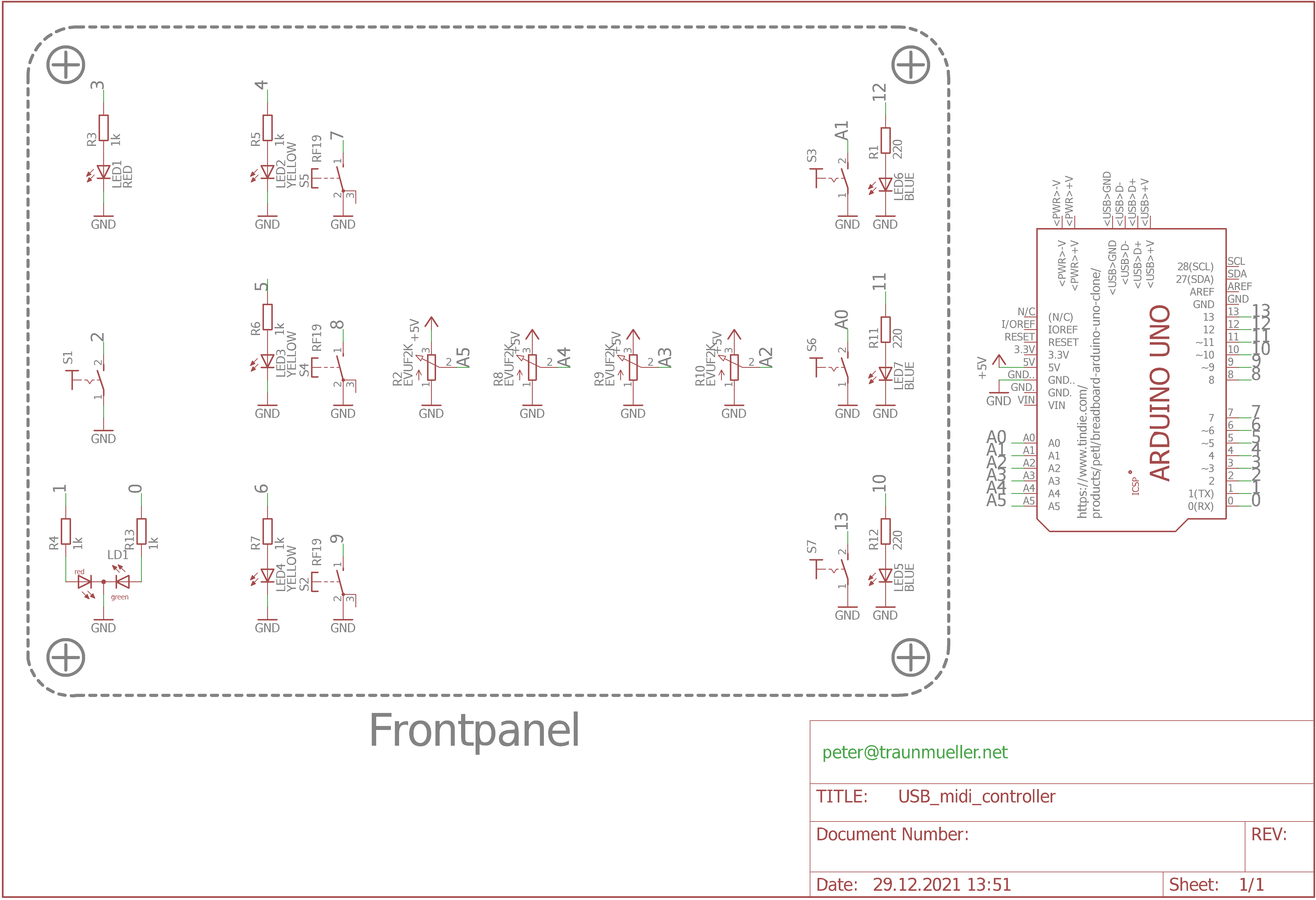 Schematics.
Software
As most Arduino clones don't have a dedicated USB microcontroller, I opted for a virtual Midi port. This means that the CH340 on my clone opens a virtual COM port on my machine and an additional software converts it into a Midi port. The software used for this is called hairless Midi and works like a charm directly out of the box. It has a Windows, Mac and Linux version, so no stress there.Code:
Coding wise this project is as simple as it gets. I wrote it as a long loop so it can be easily modified also by non coding people. Just take a look at the github page and scroll through.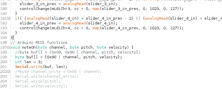 Screenshot of the code.
Mixxx:
Mixxx is quite chill about different midi inputs. I used the learning wizard to choose the controls I wanted to be controlled by the USB midi controller. It took a couple of minutes to have all the buttons, switches and sliders mapped onto the right elements. Afterwards everything worked like a charm and Mixxx saved my settings in a nice file.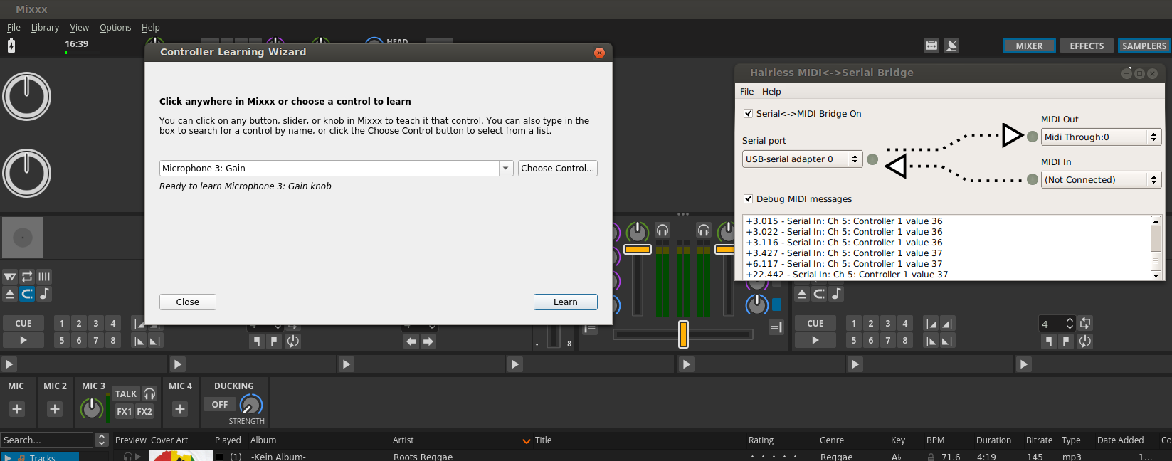 Screenshot with Mixxx and hairless midi.
Conclusion
So that's that, I hope this guide didn't get too long. All the files are on github so you can download them and browse through. Thanks to the original tutorial I was loosely following. If you have any questions or feedback just write a message or leave a comment <3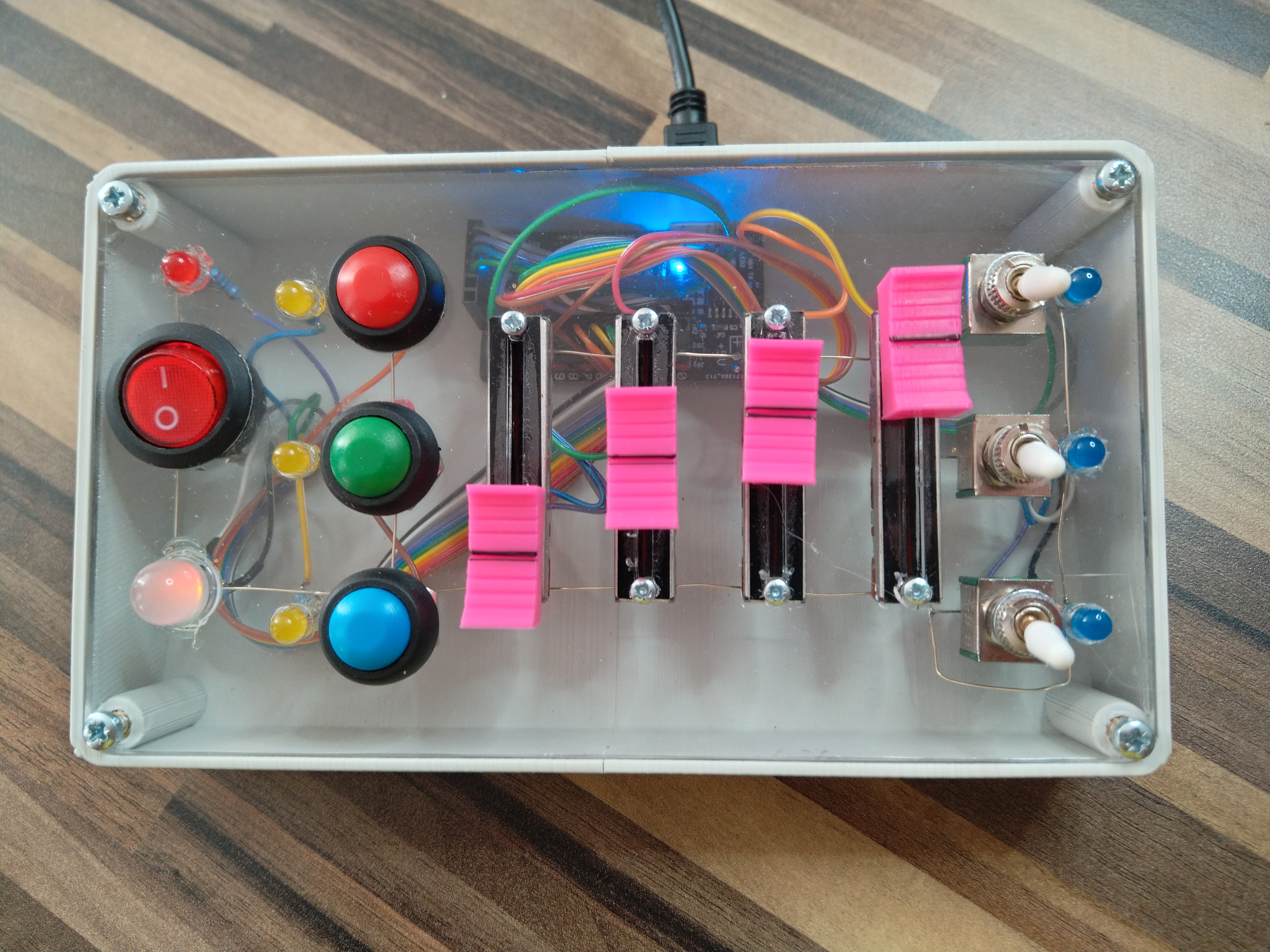 Less glamorous shot of the final product.
mRNA vaccine badge
by QC
Posted on Tue, October 19, 2021 - 09:53:04 PM
Motivation
This project started in my mind a while ago, but after /u/Almoturg made a post about a little badge that shows the mRNA of the two most popular vaccines, I immediately thought that I wanted to make this item and add some features I'd like.
Hardware
The micro USB on the back is for recharging a LiPo cell. The circuitry features over charge-/discharge, temperature and short circuit protection.
It takes a couple of minutes to run through the whole sequence, but the battery should last over 100hours. It plays the sequence once and goes to sleep afterwards, the vaccine can be changed (Moderna / Pfizer) by keeping the button pressed while turning the badge on.
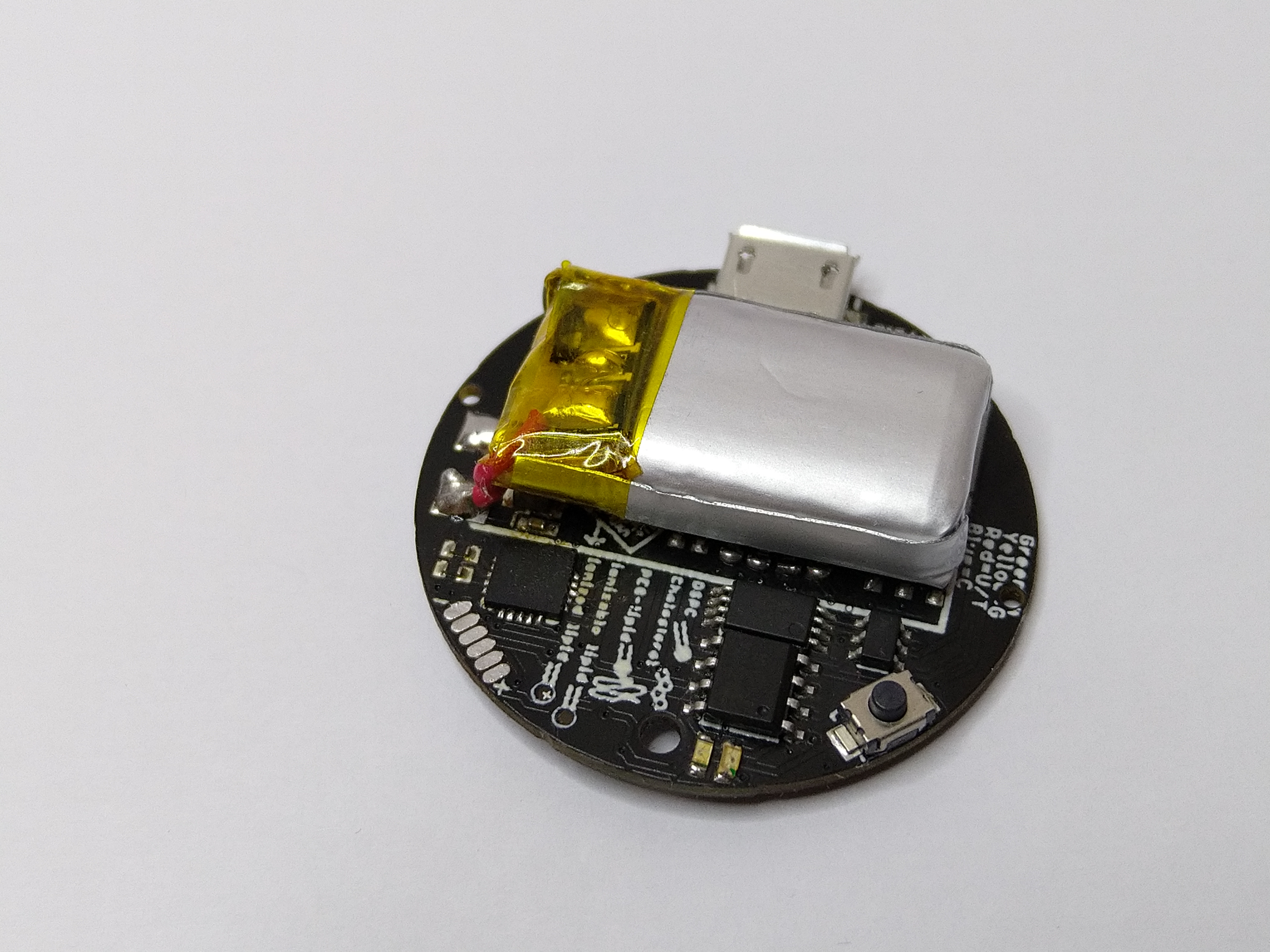 Backside with LiPo cell soldered on
The sequences are stored encoded into 2 bits per nucleotide using encode_genome.py.
Schematics:
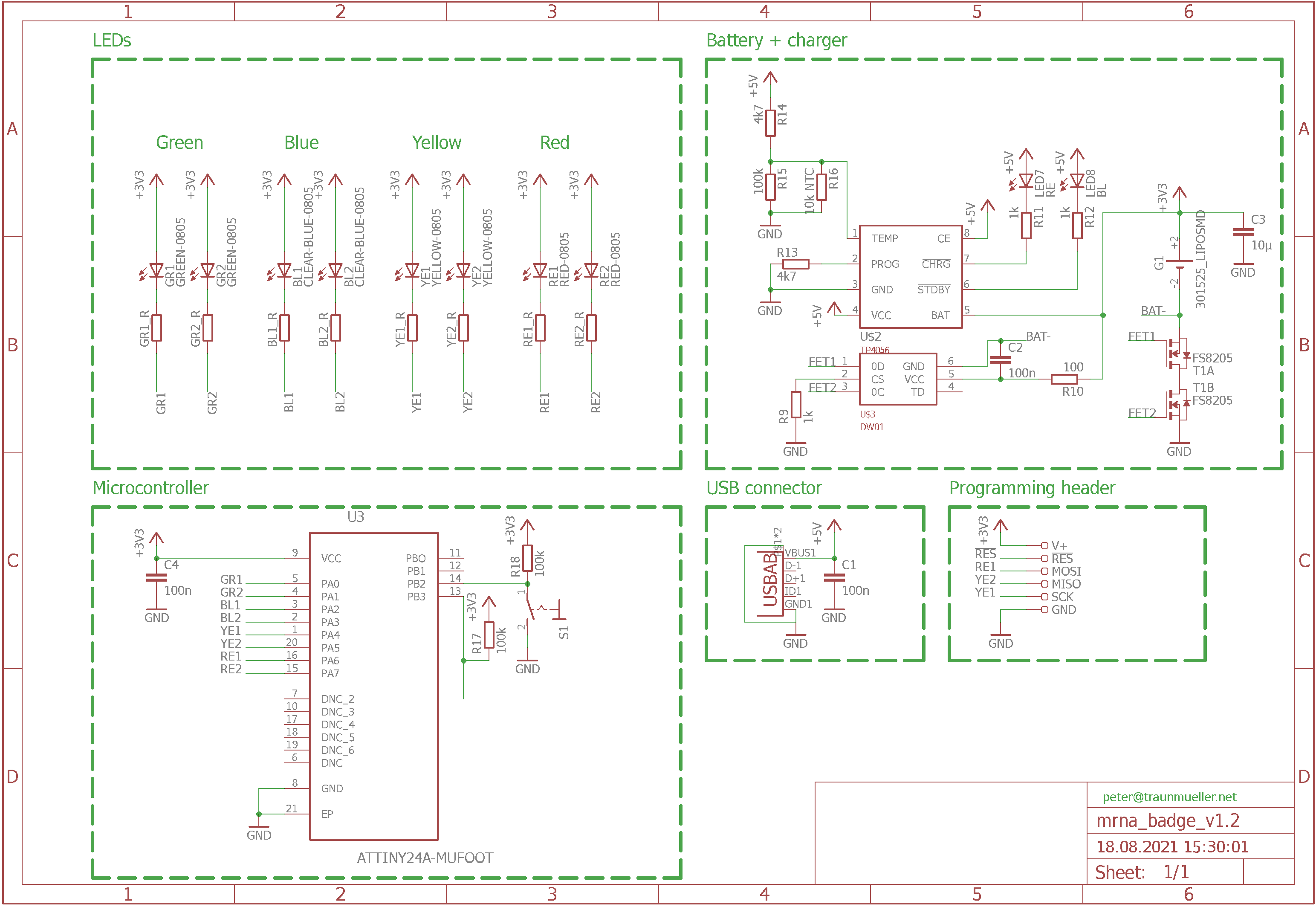 Version 1.2 of the schematics.
- Microcontroller can be programmed via Arduino over the Atmel ICSP programming pinout. Can be drop-in replaced with ATTiny44/ATTiny84.
- Li-ion LiPo battery has a charge/discharge/overtemperature and short circuit protection.
- Battery charging indicators on the backside.
- Micro USB for charging.
- Button (Momentary Switch) is hooked to an interrupt.
- LEDs are not multi(/charlie)plexed for easier programming.
Software
I've rewritten all the code for the Arduino IDE to be compatible with the ATTiny44, or its bigger brother ATTiny84.The new design files are on github where the project was forked from. Since there was a lot of interest the last time about buying them instead of DIYing, there are a couple of pieces on tindie.
Video
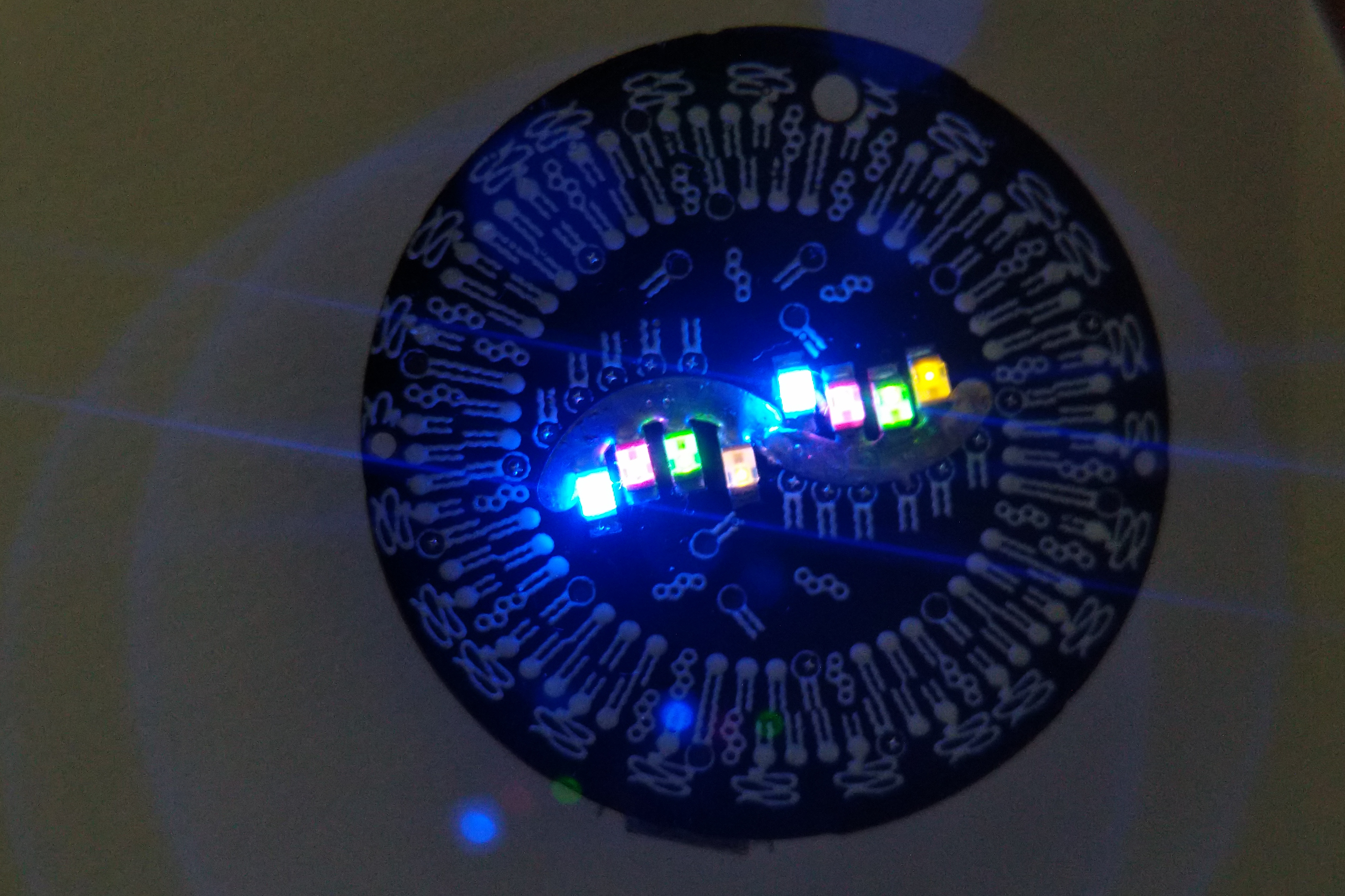
A short clip of the badge to get a feeling: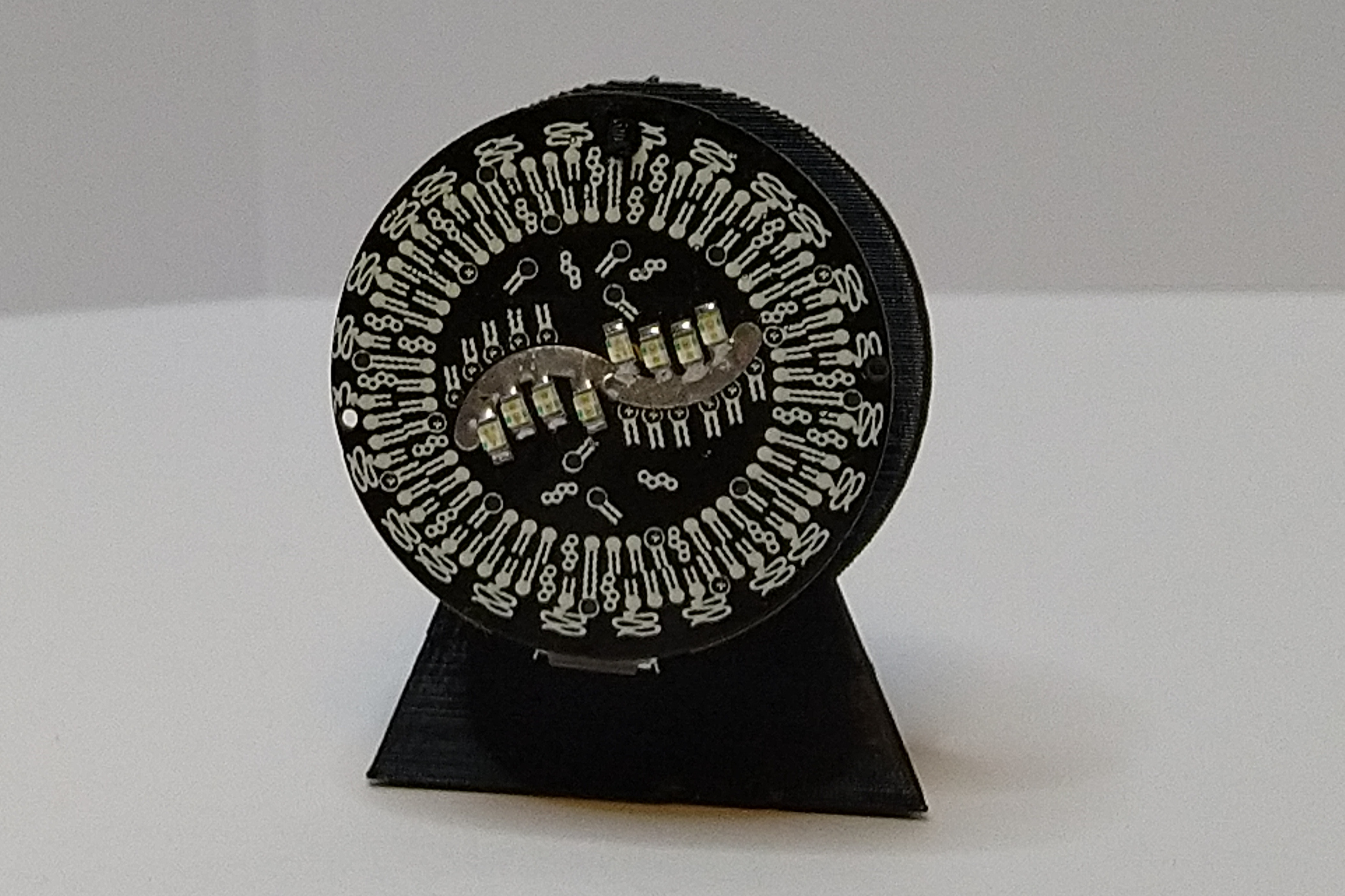 The unit in action (VIDEO)
The RNA for the moderna vaccine is from is from https://github.com/NAalytics/Assemblies-of-putative-SARS-CoV2-spike-encoding-mRNA-sequences-for-vaccines-BNT-162b2-and-mRNA-1273 with an added poly-A tail of similar length to the Pfizer one (just a guess). The Pfizer sequence is from https://berthub.eu/articles/11889.doc
There are always two nucleotides shown, one on the left 4 LEDs and one on the right:
A = Green
G = Yellow
U/T = Red
C = Blue
Conclusion
So that's that, I hope this guide didn't get too long. All the files are on github so you can download them and browse through. In case you are interested in just buying a fully assembled piece, they are on tindie. If you have any questions or feedback just write a message or leave a comment <3 Read MoreRechargeable LED bicycle helmet light
by QC
Posted on Tue, August 24, 2021 - 06:41:01 AM
Motivation
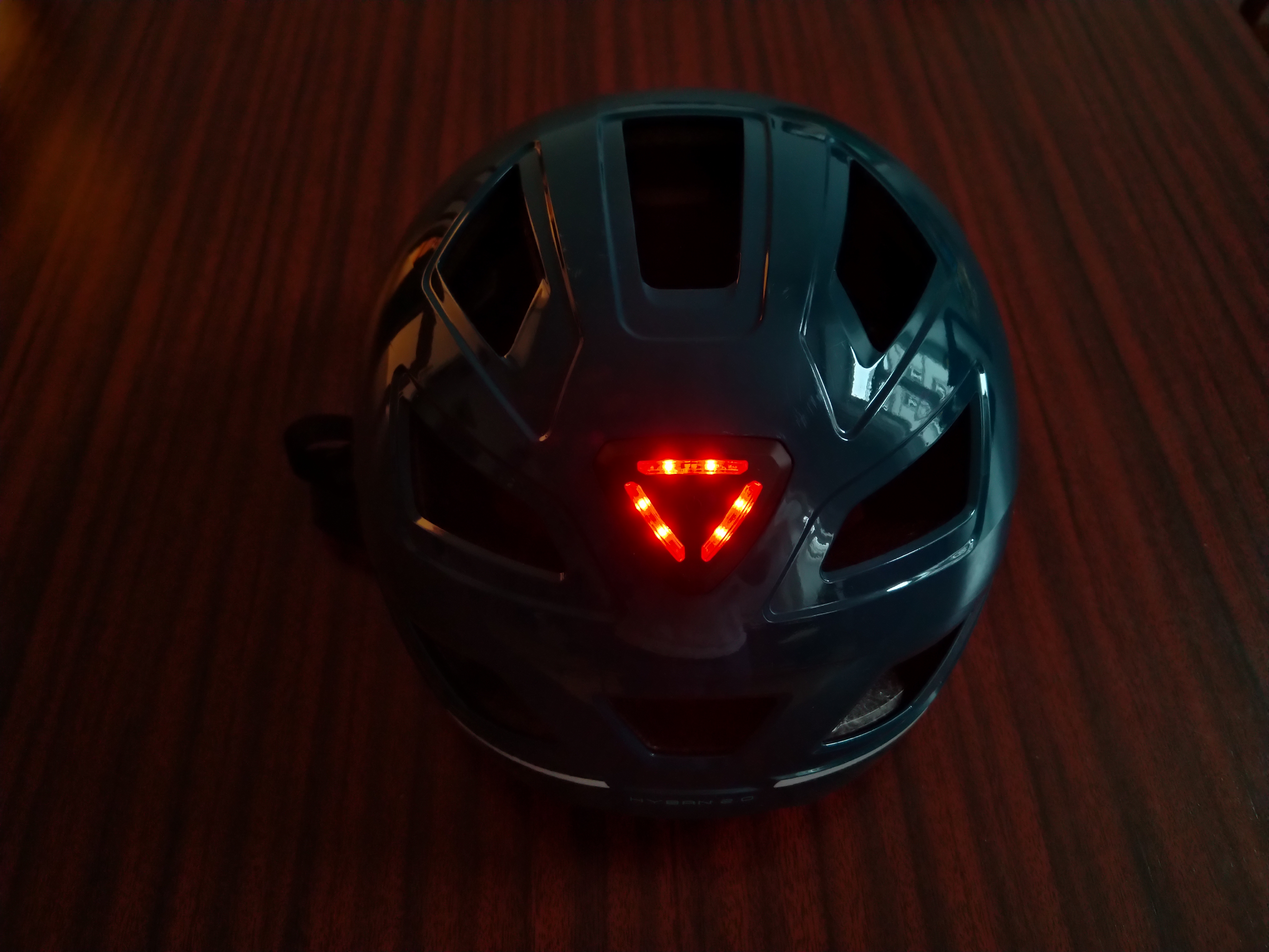
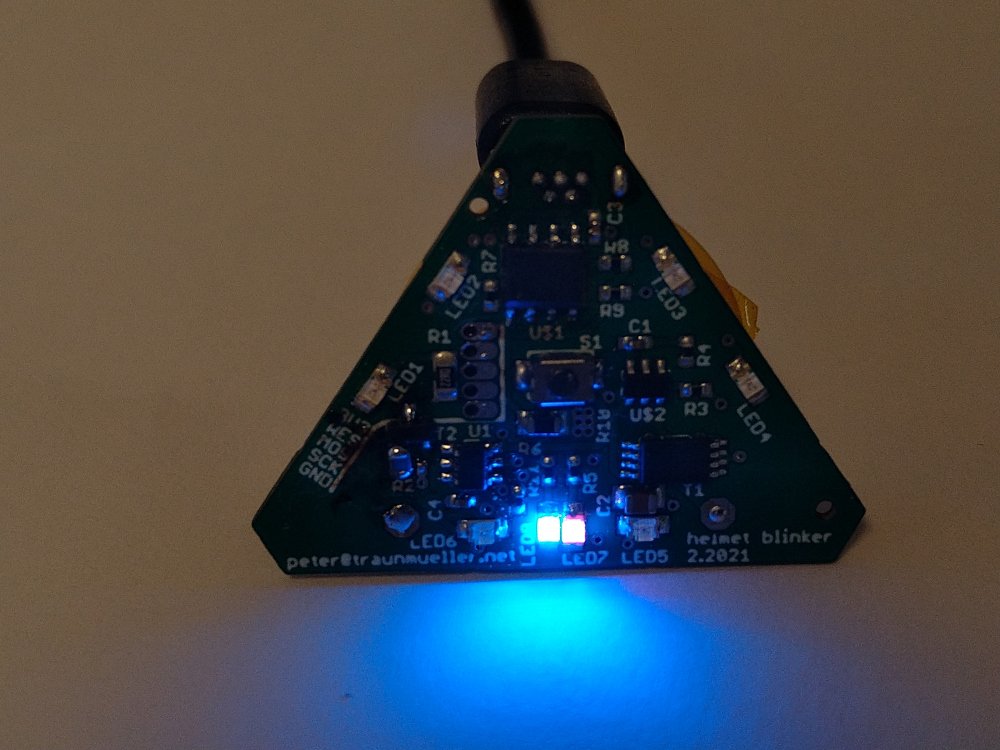
Last year I got a new helmet to make cycling for myself a bit safer. The helmet is an ABUS Hyban 2.0 in a stylish color with an integrated LED backlight, which helps others see me at night. Unfortunately the original light is powered by a single CR2032 coin cell, which not only limits its runtime severely, but also is not rechargeable. There even is a video on how to change the coin cell. This itself is just how ABUS makes products, but what really dumbfounded me were the misaligned LEDs. They just light straight into the rubber part of the light and only some scattered light can be seen from outside. Interestingly enough, the light made it to version 6 as the photo below shows "ACHV_V06".Long story short: I made a rechargeable drop in replacement for the original light.
If you're interested in this project, take a look at the github or the Tindie page to buy one, or just write a message or leave a comment.
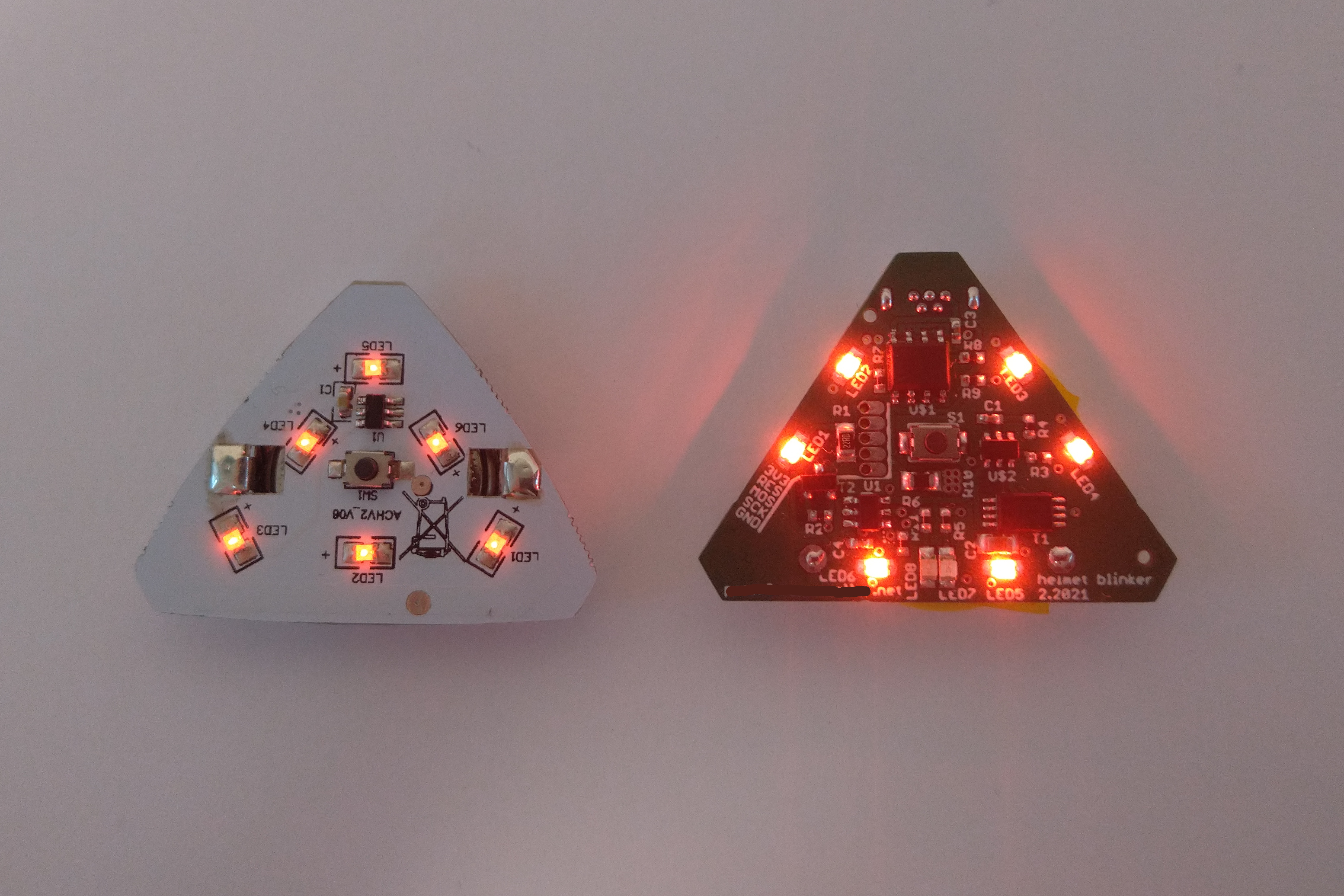
The original light on the left, the new one on the right.
Schematics
There probably is a reason why the original light was not rechargeable and it's most certainly money. The most complex part for the PCB was the charging solution around the TP4056 IC. The LiPo is fully protected: over- and undervoltage, temperature limit and short circuit. There is not a lot that can go wrong anymore with the battery which is a reassuring since it is worn near your head.Besides this, the most interesting area is around the ATTiny10 microcontroller. It get programmed via a programming header which I made myself out of some pogo pins. It can detect the push button being pressed and then run some funky blinking on the six red LEDs.
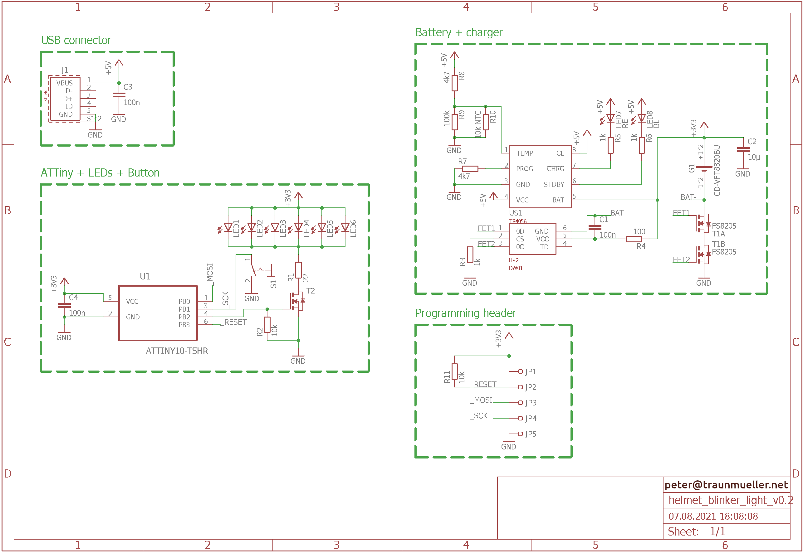
Schematics for v0.2.
Hardware
The hardware assembly was mostly done by jlcpcb (unfortunately not a sponsor). I only had to do the battery and USB connector. The connector itself is a 90° micro USB which snugs in perfectly next to the battery and rubber protector. A great amount of measuring wnet into the correct positioning of the 6 red LEDs bedind the plastic reflector. This worked out surplrisingly well as the can be individually seen in the top photo.
Backside of the light while charging
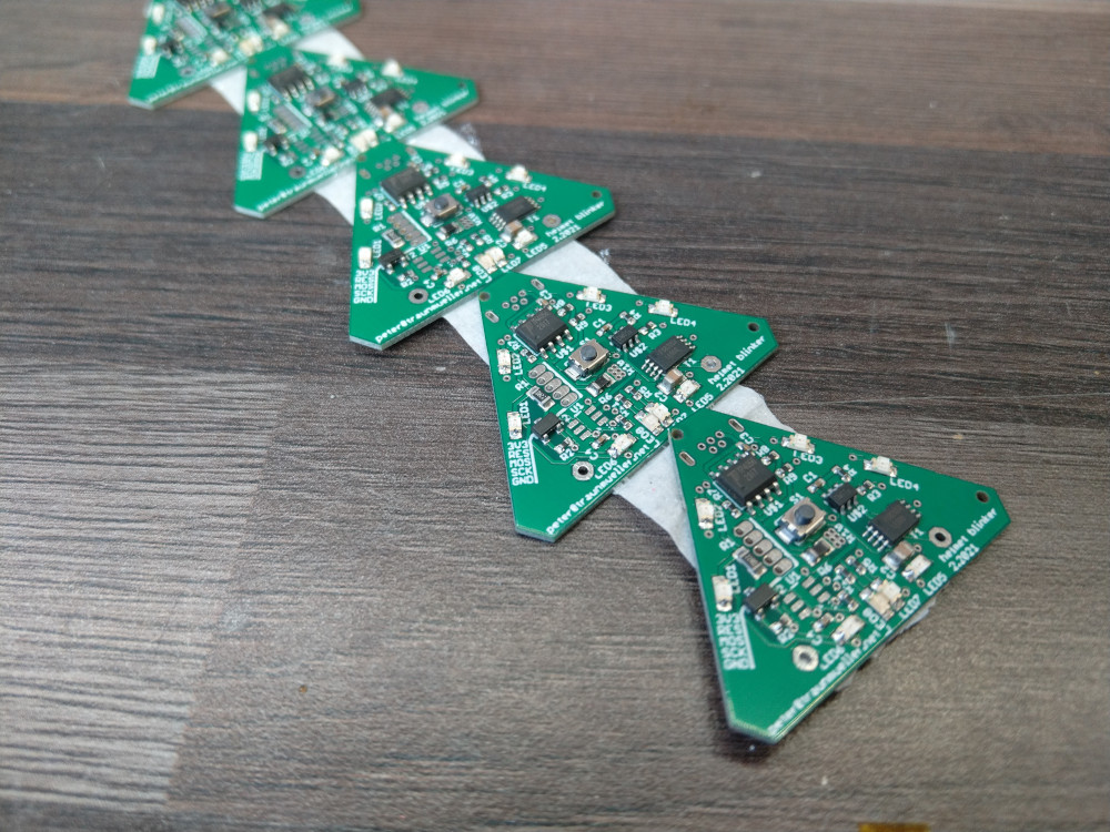
PCBs to make more lights.
Charging indicators for the LiPo cell.
Software
Programming an ATTiny10 was more challenging than expected. Although it is an Atmel microcontroller out of the AT* family it behaves quite differently than the ATTiny 84 or 85 for example. It does not feature a real ICSP programming input and can therefore not just be programmed with the Arduino IDE and a library. The programming protocol is called TPI (Tiny Programming Interface) and luckily technoblogy already worked that one out, big thanks to them! It only took me almost a week to find their solution and order the recommended "USBasp" programmer, so use this information wisely. After that is is quite straight forward, a lot of low level register magic combined with the incredibly low power deep sleep of the tiny. There are 4 different modes which are cycled through by pressing the button:
- 1: 100% on
- 2: 50% on, 500ms period
- 3: 20% on, 300ms period
- 4: 3% on, 1000ms period
Screenshow of the code: source .
Runtime
The most important question was the possible runtime of the setup. The battery used is a 3.6V 120mAh LiPo which drives the 6 LEDs at ~10mA each, the ATTiny draws 0.2mA while running. This means that in mode 1 it can do roughly 2h on a single charge. In mode 4, this runtime goes up to 65h, since it is only pulsing the LEDs.
Standby time can be calculated with the deep sleep current of the ATTiny of <0.1µA. This would result in 1.5 million hours standy time.. More realistically the rest of the circuit uses more current and limits this time. It still is an impressive number and will definitely be the clickbait in case I make a video about this.
Conclusion
So that's that, I hope this guide didn't get too long. All the files are on github so you can download them and browse through. I did contact ABUS Germany about my design and the idea to make their products rechargeable, but they never answered. So now it is on my Tindie page. If you have any questions or feedback just write a message or leave a comment <3 Read MoreOptical character recognition with tesseract on a raspberry pi
by QC
Posted on Fri, March 26, 2021 - 11:56:54 AM
Motivation
How do you track people coming and going into rooms during Covid19? Right, you save the RFID tag off their ID card! Thing is, not all IDs have RFID and more so, not all of the tag IDs are easily matched to user IDs.. To get around this we can just take a photo and read off any number we want. That's easy and quickly modifiable for different ID cards.
Long story short: The project uses tesseract to do optical character recognition (OCR) on a photo taken from the ID card. This is then fed into a server which saves the original picture with the read number.
If you're interested in this project, take a look at the github repository or just write a message or leave a comment.
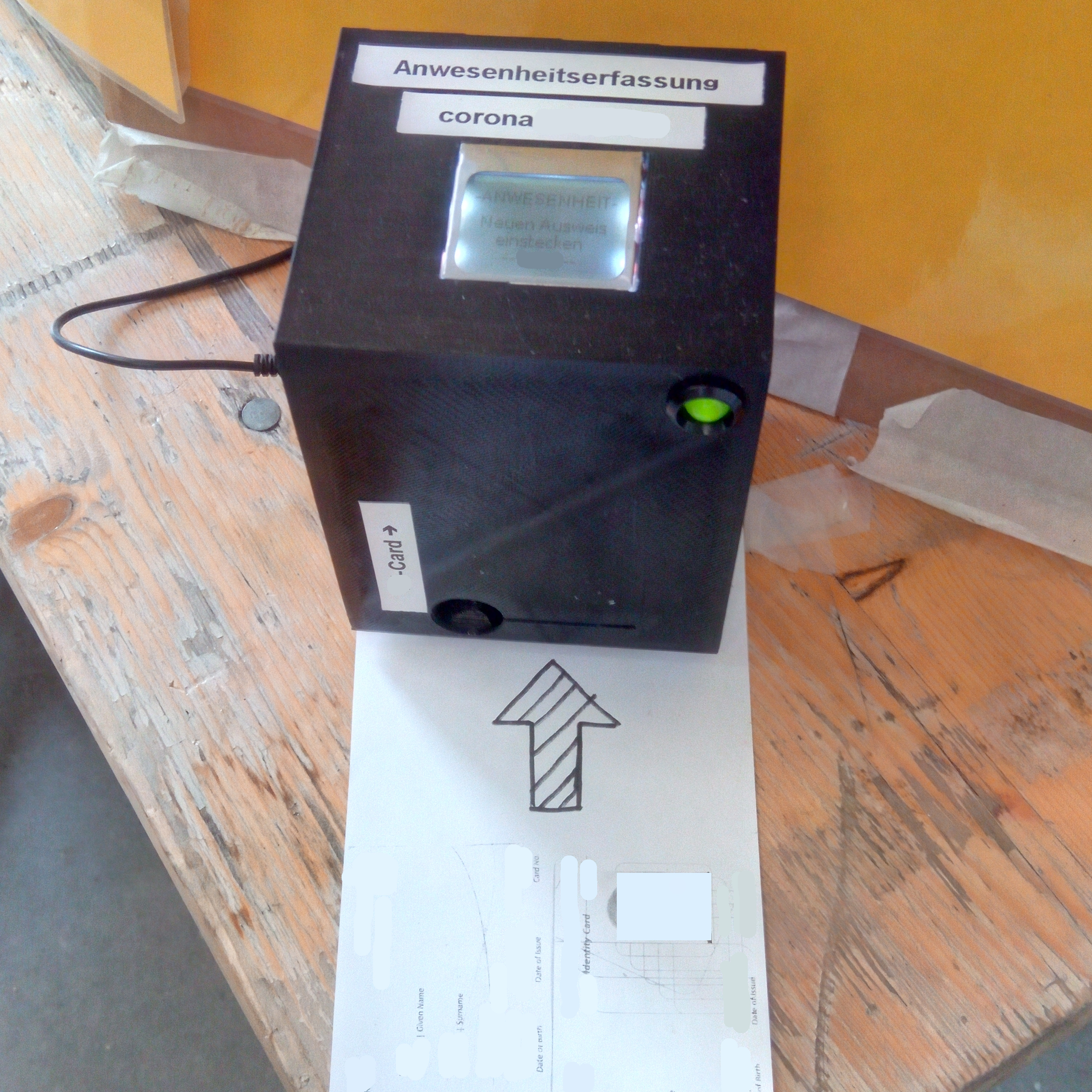
Photo of the reader in action.
Hardware
The stuff you have to buy is quite straight forward:
- Raspberry Pi zero with SD card
- Raspberry Pi cam
- Display Nokia 5110 / PCD8544
- 2x LED white
- 1x LED greed/red
- 3x 220 Ohm resistors
- 2.5mm DC barrel connector
- Some wires and heatshrink tube
- 4x M3x12 screws
I'm not including part numbers as most of the stuff was bought from ebay and can be found by posting the description in the searchbar will find the cheapest option.
3D printed hardware
The case is made out of two 3D printed parts. They are optimized to use as little filament as possible and don't need any support while printing.
If you take a look at the rendering, you can see that the case is mostly empty. The inner chamber is on the top equipped with the camera and one or two LEDs and on the bottom the ID card can slide in from the front. This ensures that the camera always has the same perspective and reading stuff off the picture is straight forward. Around the inner chamber I've left enough space to fit in all the electronics and wires. The final design has two sand filled bags on each side to weigh everything down. Otherwise the box gets shifted around while inserting the ID and feels quite flimsy.
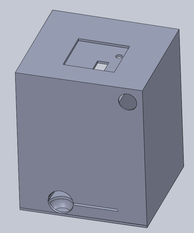
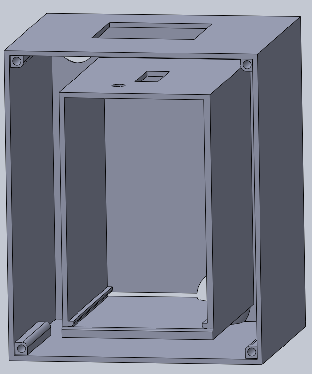
Rendering of the main 3D printed part.
Electronics
The reader was designed to use as little electronics as possible. This reflects in not using an eject mechanism or endswitch for card detection. It has an old Nokia 5110 Display which is super cheap on ebay and a two colour LED for user feedback. There are no buttons or any option for the user to interact with the unit, besides pushing in an ID. The schematics are below, note that the two white LEDs are just for illumination purposes.
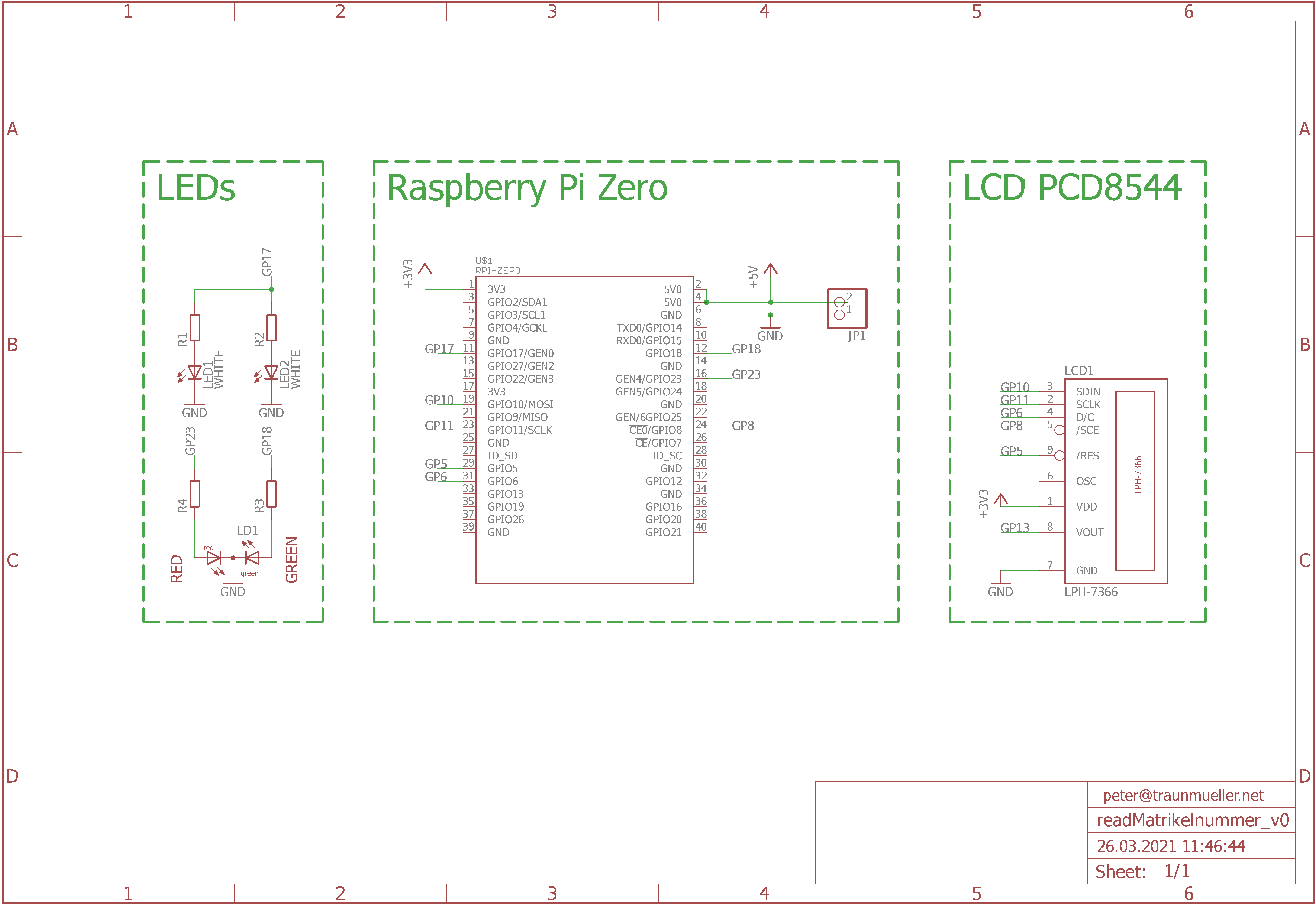
Schematics.
Software
Obviously all the code is written in python. Actually it's not that obvious, but there is a nice library doing most of the tesseract interaction for me, so that's that. Please note that the guide includes training data. I've trained the tesseract according to some tutorial and would not recommend you doing so unless you have a good set to start with. I've done training with a limited set of a few cards and it actually made the OCR worse. To get everything running, you can work your way down this list:
- set up the RPi
- > sudo apt get update && upgrade
- > sudo apt-get install tesseract-ocr
- > sudo apt-get install python3-pip
- > sudo pip3 install pytesseract
- > sudo pip3 install picamera
- > sudo pip3 install adafruit-circuitpython-pcd8544
- > sudo apt-get install ttf-dejavu
- > sudo apt-get install python3-pil
- optionally, if you have training data: > sudo cp /home/pi/tesseract_training/tesstrain/data/USERcard.traineddata /usr/share/tesseract-ocr/4.00/tessdata/
Before you can start, you need to enable SPI, SSH and the camera in the Interface options of:
> sudo raspi-config
To run the code, start it with start_readMatrikelnummer.sh from the github.
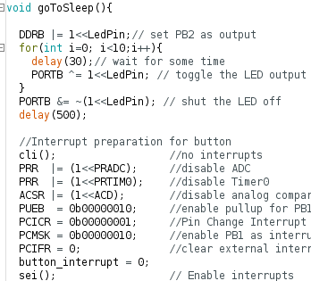
It continuously takes photos of the chamber and compared the right most edge brightness to a set value. If this gets bright enough, it takes a photo. This is shown by blinking the red/green LEDs and the photo is saved. After the Photo is taken, the display tells you to take out the card and stops the blinking. Parallel to that it cuts out the part of the image where the interesting number could be and does an OCR on that. If it doesn't detect a plausible number, it takes a second part of the image and does the OCR there. This routine can be expanded infinitely for different cards with different positions for the numbers. If it at some point detects a valid number it opens a URL to upload the number and corresponding image to a server via PHP.
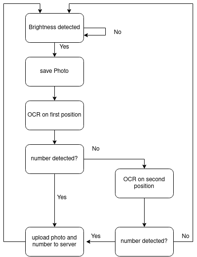
Flowchart for the code.
Server
If a plausible input is detected, the image and number get uploaded to a server via PHP. The server side is really low level and doesn't need a database or any other thing besides PHP. It checks all the uploaded items for their creation date everythime someone opens the page and deletes everything that is older than 14days.
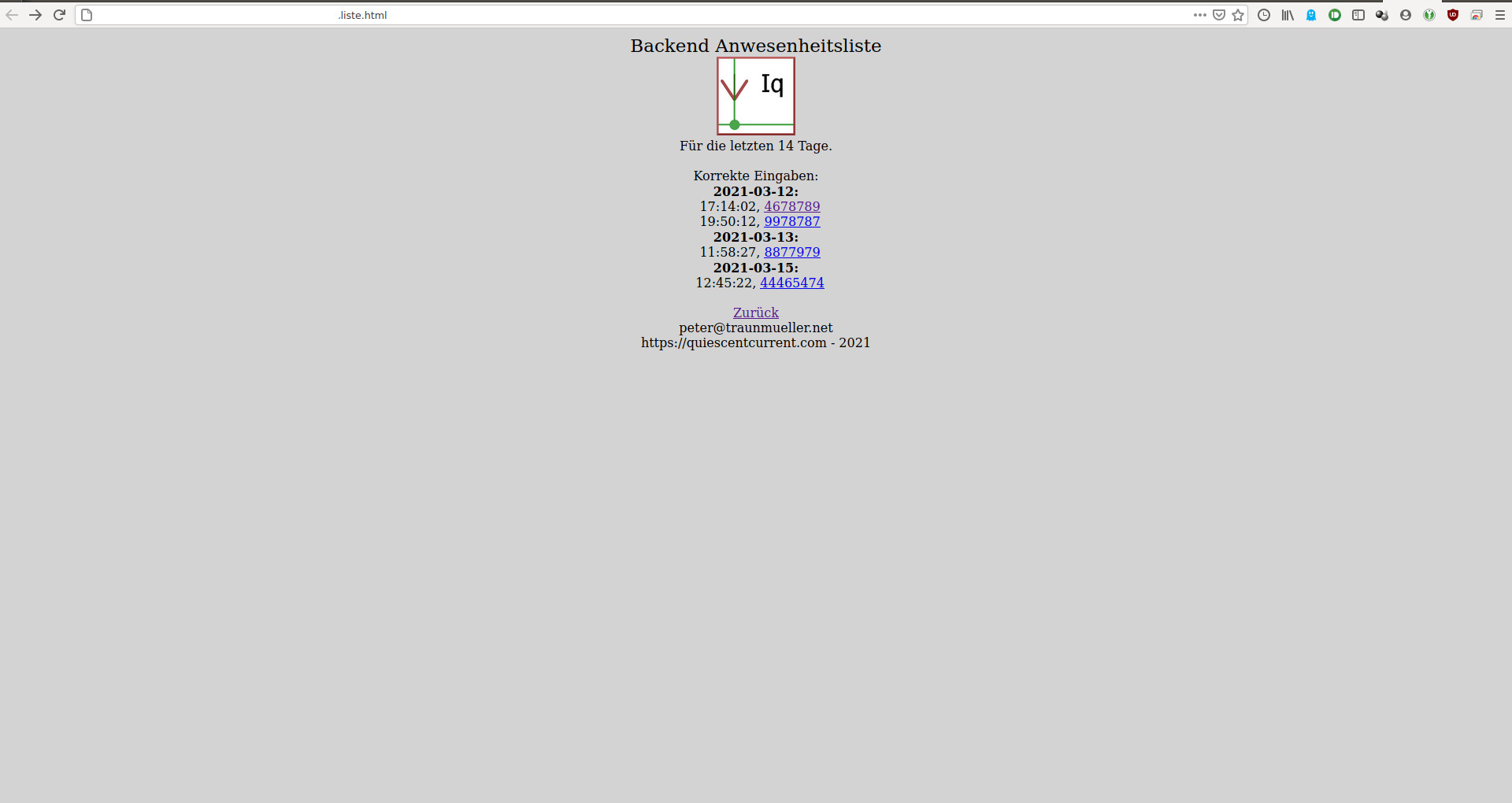
Backend on the server.
Assembly
Bringing everything together is not difficult and only requires some hot glue. Due to the spacious inner part of the box, all the cables and the pi perfectly fit with still some space left.
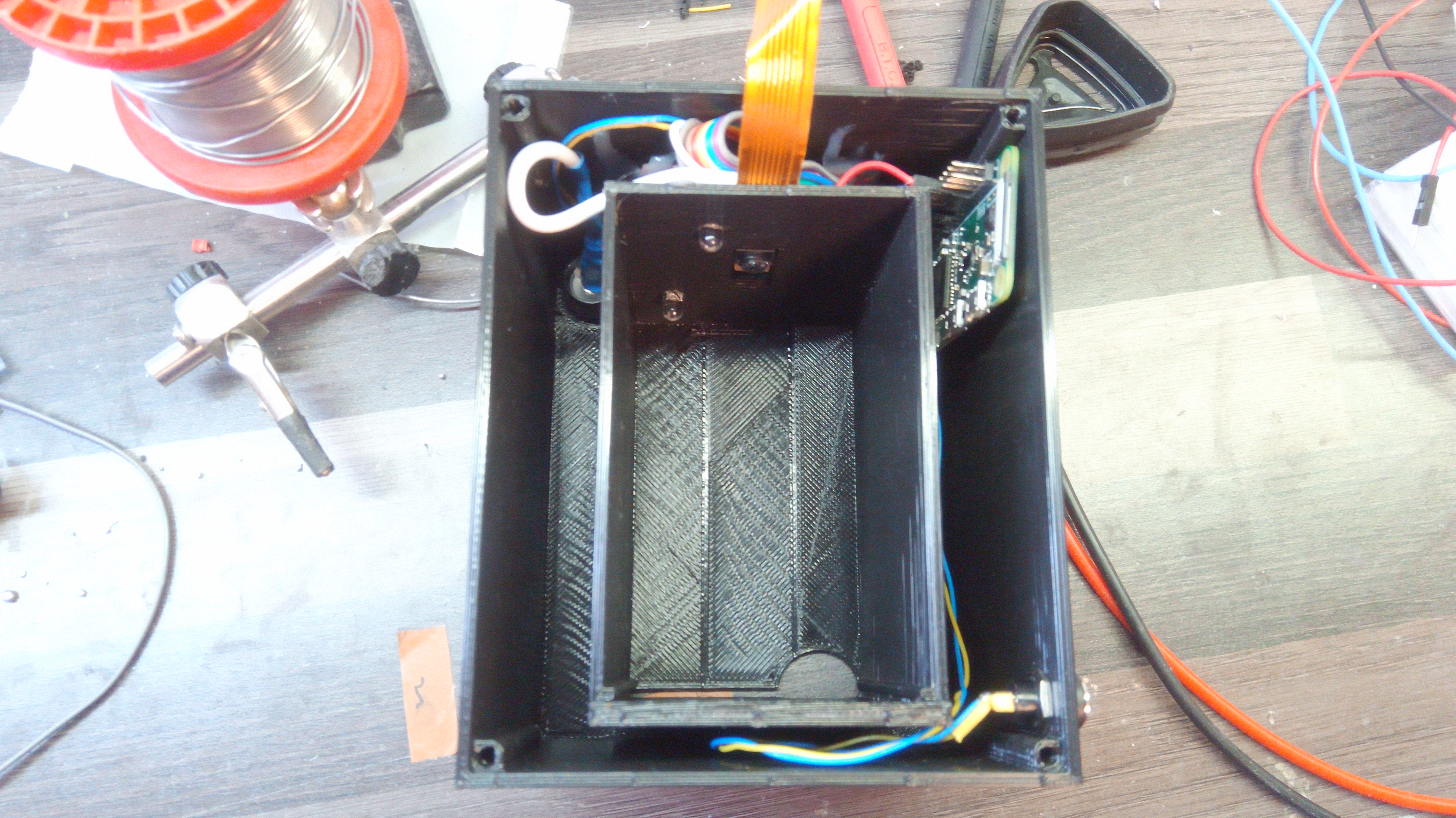
Half assembled unit.
The additional space is then filled with two sand filled bags to make the unit heavier and give it a more robust feeling.
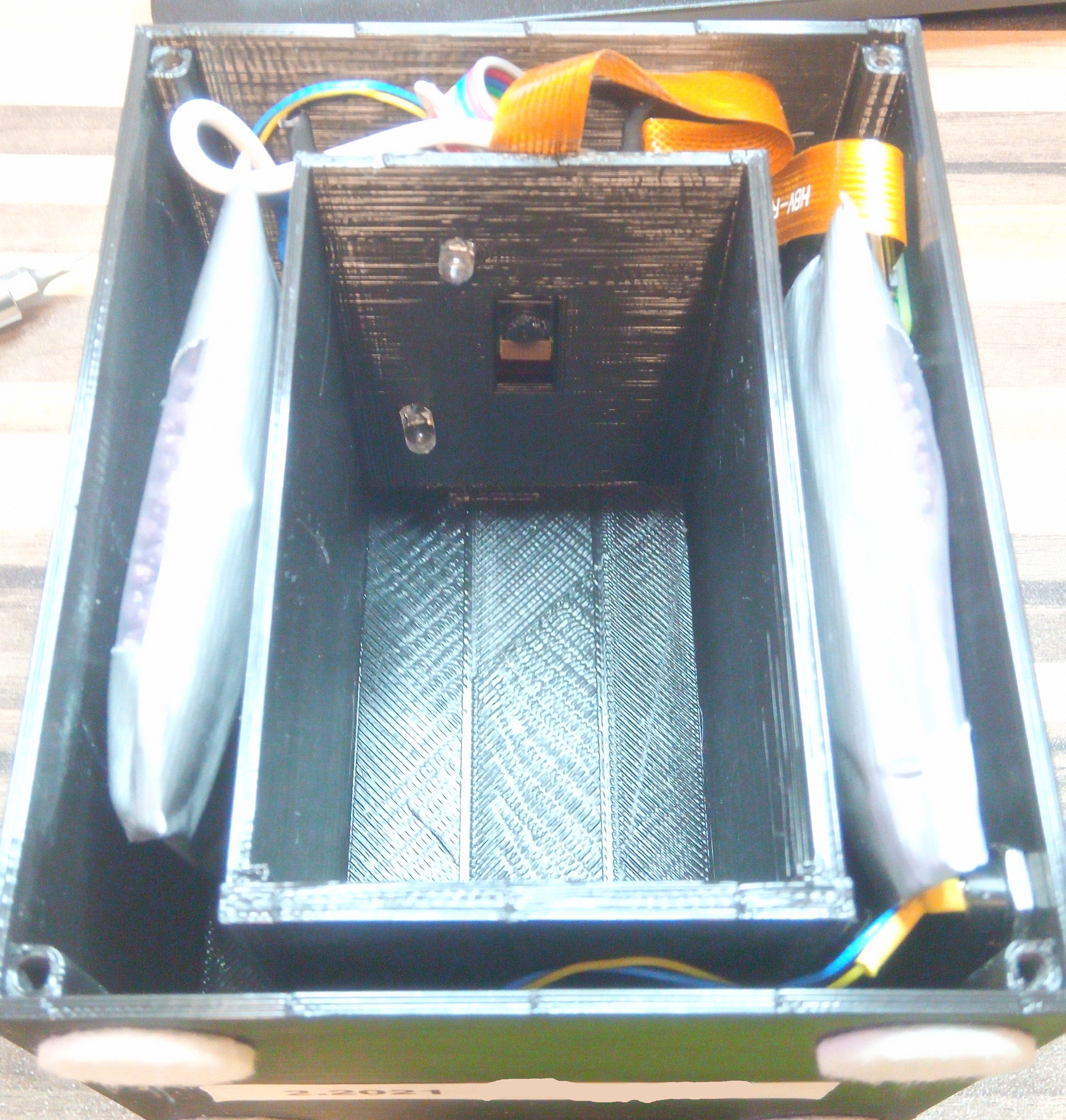
Unit with sand bags in place.
Conclusion
So that's that, I hope this guide didn't get too long. All the files are on github so you can download them and browse through. If you have any questions or feedback just write a message or leave a comment <3 Read MoreRAID6 on an iSCSI - Raspberry Pi
by QC
Posted on Fri, October 09, 2020 - 06:36:09 PM
Motivation
How doesn't want a huge RAID in their living room? Lots of people certainly do and getting a NAS at a fair price is often complicated. This one time at band camp... no. We're here to get to know how I had to unfuck a Raspberry Pi 4 after getting it stuck at boot after enabling iSCSI auto start. But let's start at the beginning.
Intro
While hosting a bunch of stuff, the word backup is thrown around quite often. Every tutorial I've read includes something on the top consisting of backup all your data before starting or alike. The professional admin I am, I never did, and had to fiddle around a lot to get stuff working again. This led me to the point where I bought a desktop RAID1 to backup the most important stuff at home. As it has to be, those two poor drives got used a lot and soon turned out to be too small. During this time I also developed some motivation for real backups and told myself that the next system I'm going to buy would need to be a RAID6. As those things are not cheap in any way it took me a while to find a promising candidate.Hardware
Then, the other day (like two months ago) I got two A12E-G2121 Disk Arrays from the local Craigslist equivalent for cheap. The seller was a really nice dude and even let me know that iSCSI is officially pronounced "EYE-skuz-ee".These SATA to iSCSI modules made by 'Infortrend' provice access to SATA drives over the network. They have a RAID controller built in, which can do up to RAID 5 with a cold spare. Unfortunately due to their age, there is virtually no information or documentation for them available on the net. I had pieced together some fragments of the manual over shady manual-hosting-sites, before directly asking the manufacturers techs to send me over some infos. Luckily they actually did that and I now have a complete manual, latest firmware and configuration tool for the thing, just shoot me a mail to get access: iq.quiescentcurrent
 gmail.com
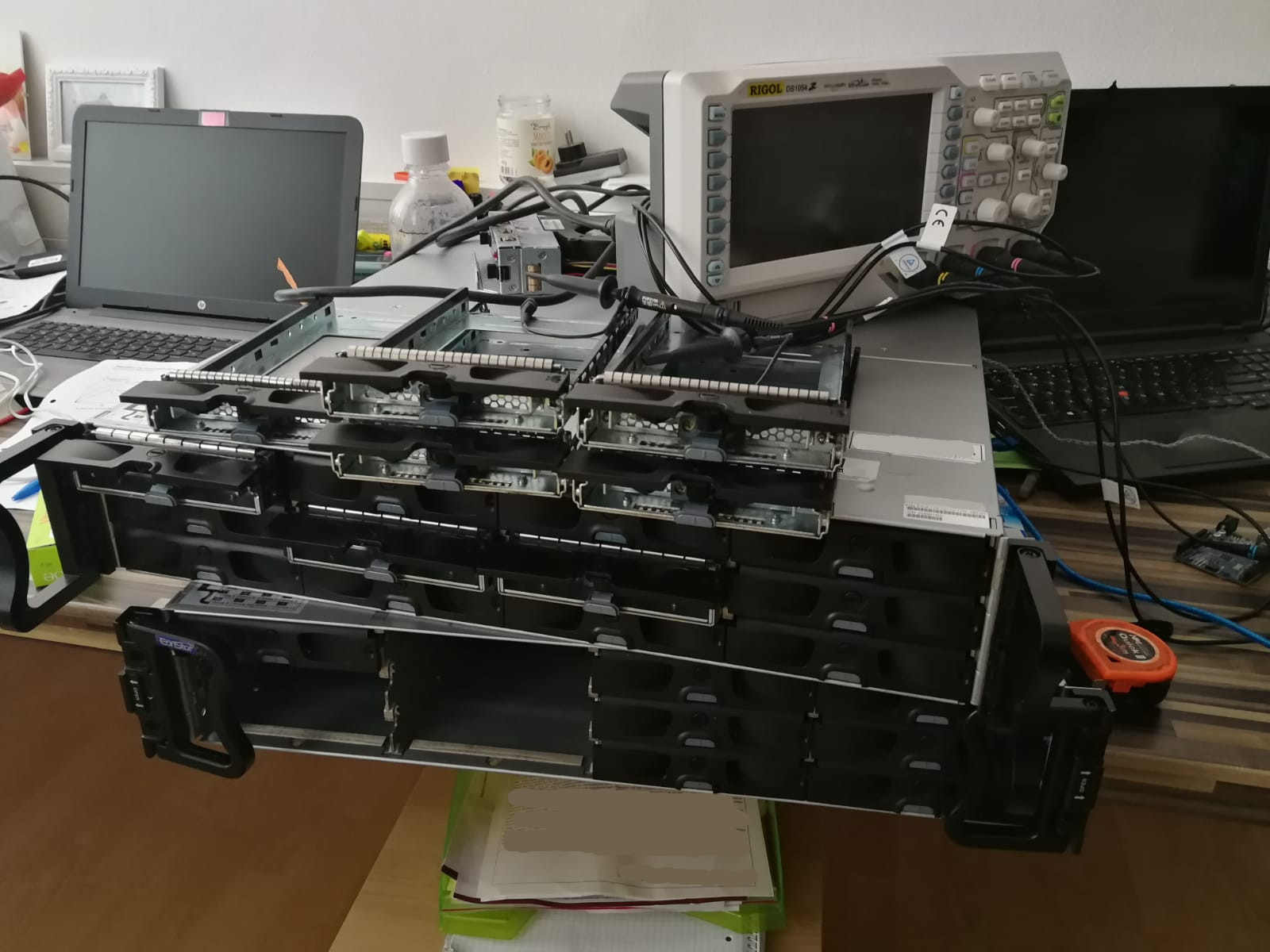
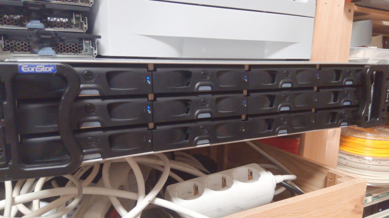
Photo of the rack
Don't forget to buy some HDDs, minimum of 4 for a RAID6, but the more the merrier. Also keep some spare ones in case you have a failing disk on a Sunday afternoon. Also it is recommended to buy dedicated drives often called 'NAS drive', '24/7',... Every manufacturer has their own line of 'higher quality' drives for this application.
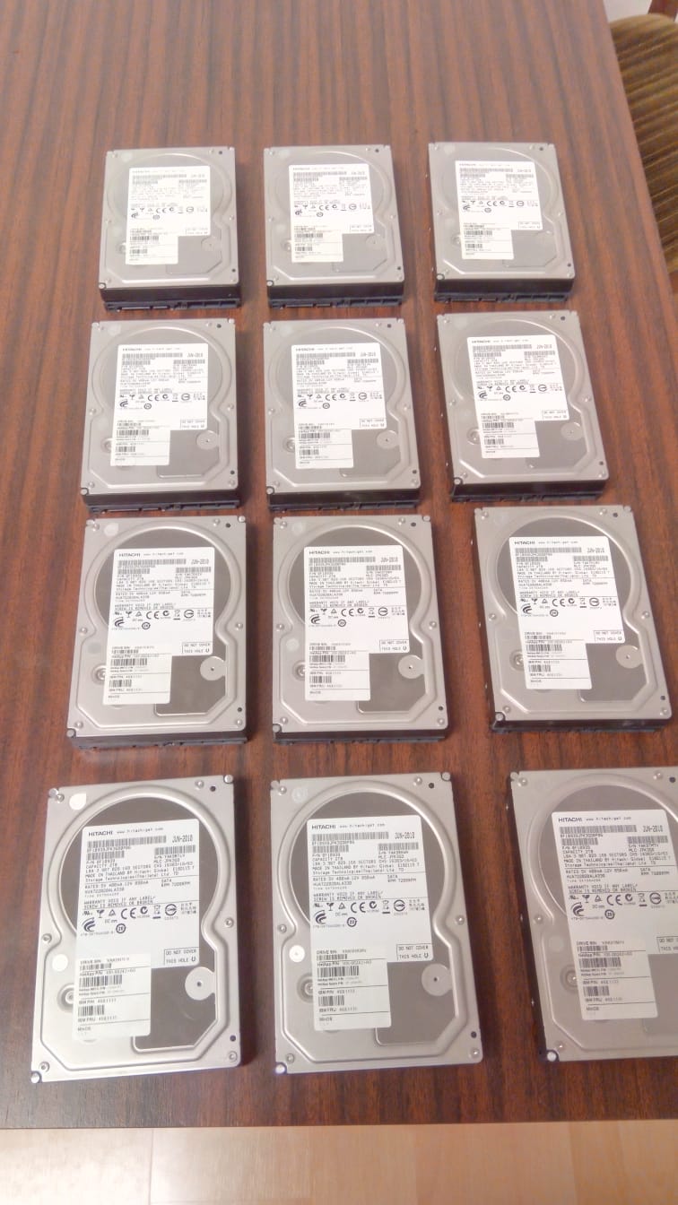
12 HDDs
For the RAID I decided to use 8 disks, that makes the space of 6 usable for me. The 4 others are kept as spares, or until we need more space.
Software Setup
The picture above shows an oscilloscope for a reason. If you haven't configured the EonStor, it will just beep annoyingly and definitely be not accessible over your network. There is a 3.5mm headphone jack on the back which offers a serial connection over RS485. This is the only way to get terminal access to the thing and I had to get some serious scope readings to be able to give you this knowledge.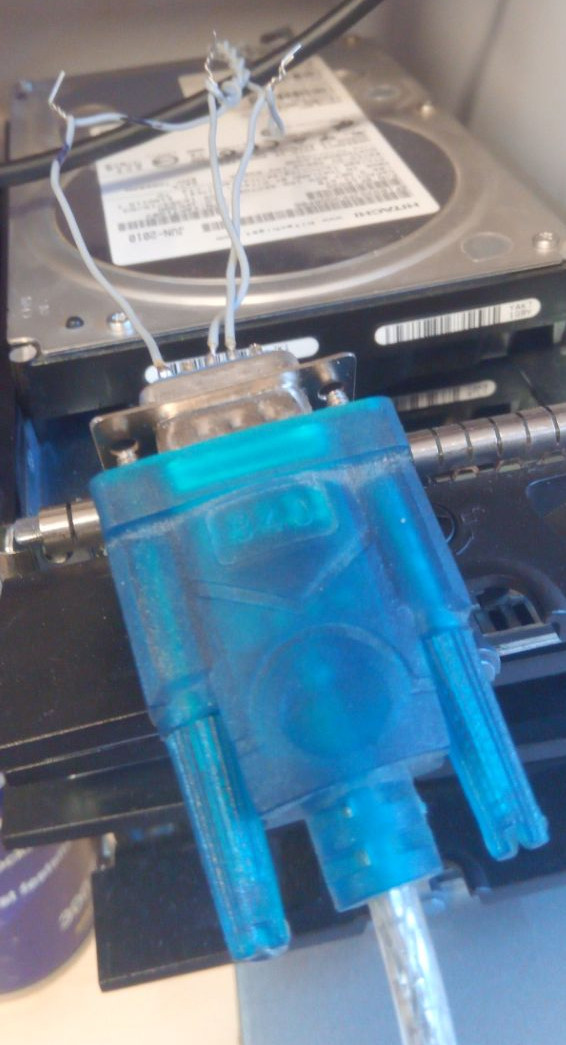
RS485 with a DB9 to 3.5mm jack adaptor contraption
With this I got to open a terminal and type the holy words:
> cu -l /dev/ttyUSB0 -s 38400
which offered me this beauty:
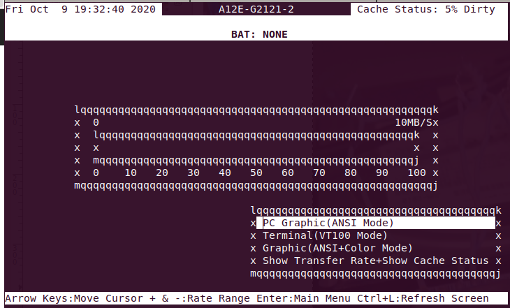
Administration Interface
From this point on I was able to configure the TCP/IP settings correctly and was able to connect over the network with ssh. The -o and -c options are legacy and not enabled by default anymore.
> ssh -oKexAlgorithms=+diffie-hellman-group1-sha1 -c 3des-cbc root@172.1.2.34
Let me tell you this is HEAVEN, finally a real connection!
RAIDWatch
RAIDWatch is the official GUI tool which can configure the disk array. It probably runs on Windows, but most importantly it works in Linux as a java application. So i let the installer run, which includes a JRE (java-run-environment) and everything, so I only was a bit of fiddeling to get it to start. Most importantly, it doesn't generate two files which prevent it from starting, so generate those manually:>touch /usr/local/Infortrend Inc/RAID GUI Tools/userconfig.ini
>touch /usr/local/Infortrend Inc/RAID GUI Tools/raidwatch.en.lang
After that, you can start the tool. To actually be able to connect to something you need to start it as root, the thing has no permissions otherwise. Add a "sudo" in front of the command in:
>nano /usr/local/Infortrend Inc/RAID GUI Tools/raidwatch.sh
and start it with
> sudo /usr/local/Infortrend Inc/RAID GUI Tools/raidwatch.sh
to fix this.
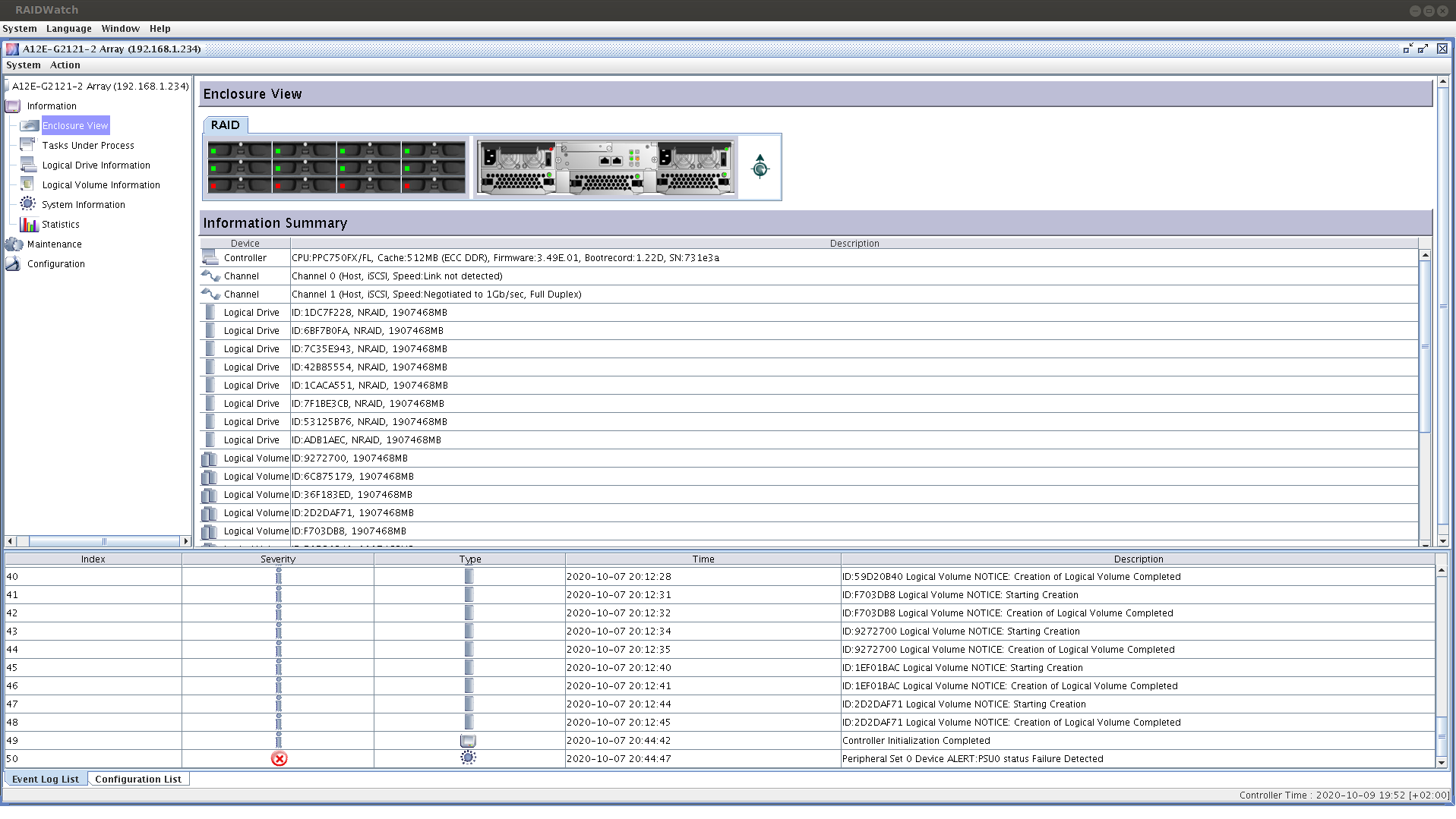
RAIDWatch GUI
Once running, RAIDWatch is straight forward to configure. Connect as "Configuration" user to get all features. It offers a Quick installation which is rather nice and lets you choose the RAID options you want:
RAID levels: 0, 1(0 + 1), 3, 5, 10, 30, 50, JBOD and non-RAID disk spanning
As I needed (read: wanted) a RAID6, I've just configured the disks and mapped them to 8 different LUNs, to be raided in software later. Make sure to have the correct channel ID according to the connected network port (I'm not kidding...).
Raspberry pi - iscsiadm
If you've never heard of iSCSI before you're not alone and probably born after its invention in 1885. This is why there are not a lot of tutorials out the describing how to automount 8 iSCSI drives on boot automatically on a Raspberry Pi. With not a lot I mean this is the only one at the time of writing this post (10.2020). This also means that I didn't have a guide to follow while setting this up (It's called paradox, look it up). Here's the steps I followed, stolen from here:> sudo apt install open-iscsi
> iscsiadm -m discovery -t sendtargets -p 172.1.2.34:3260 -d3
> iscsiadm -m node -T iqn.2007-10:iscsi.target0 -p 172.1.2.34:3260 --login
Then check if we have contact:
> iscsiadm --mode session
and see if the disks are here:
> blkid -o list
If they are larger than 2Tb use this instead:
> lsblk
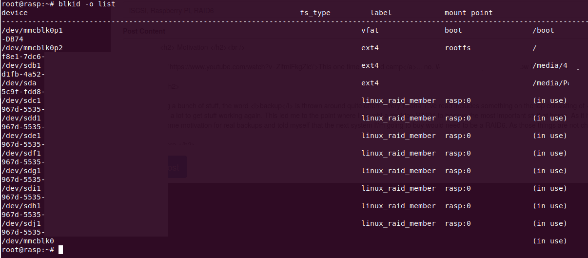
blkid with the new devices sdX
We can clearly see the 8 new drives sdc, sdd, sde, ...
To make this persistent between restarts, we want to set the iscsiadm to automatically mount. For this open the file and change:
> nano /etc/iscsi/iscsid.conf
Change node.startup from manual to automatic:
node.startup = automatic
Make sure that you have configured everything correctly. If you haven't then your Pi won't start and you have to remove the SD card and undo the changes on your computer manually. If you are sure about your config and the Pi is still not coming up, it took a while for mine to boot the first time I changed this. If it comes back up, this means we have almost won.
Raspberry pi - RAID6
Joining the disks into a RAID is actually the easy part. If you've managed to follow till here, there is no power in the 'verse that can stop you. We're firstly partitioning the drives:> fdisk /dev/sdc
Repeat this for all the drives sdc, sdd, sde,...
> apt install mdadm
> mdadm --create --verbose /dev/md0 --level=6 --raid-devices=8 /dev/sdc1 /dev/sdd1 /dev/sde1 /dev/sdf1 /dev/sdg1 /dev/sdh1 /dev/sdi1 /dev/sdj1
That's it. The RAID is being built! It may take a while though...
Check the status with:
> watch -d cat /proc/mdstat
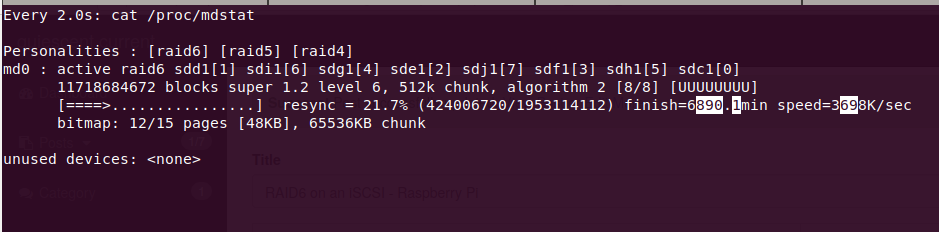
Resyncing the RAID
Yes. It takes almost 7000 minutes, that's 115 hours or ~5 days. Sit back and relax, there are tutorials on how to improve this, but none of them worked for me.
If you're restarting the Pi in the meantime, the RAID is mounted readonly to protect it. Remount it as readwrite:
> mdadm --readwrite /dev/md0
After being finished, create a file system on the device, create a mountpoint and add to to the automatically mounted devices:
> mkfs.ext4 /dev/md0
> mkdir /media/raid6
> nano /etc/fstab < add "/dev/md0 /media/raid6/ ext4 _netdev 0 0"
Watch out for the _netdev option, which specifies that the resource can only be mounted if a network is available.
Mount it and check if it worked:
> mount -a
> df -h
> mdadm --detail /dev/md0
And don't forget to add a MAILADDR so you get status mails if something goes wrong:
> nano /etc/mdadm/mdadm.conf
The final setup
DONE! You're really done, made it through the tutorial and hopefully were able to reproduce all the steps. It took me about two months including the communication with the company, buying the drives to getting everything to work. Writing this post is my part, so you can do it in one. Read More
Glow in the dark key holder knob
by QC
Posted on Wed, August 26, 2020 - 06:35:05 PM
Motivation
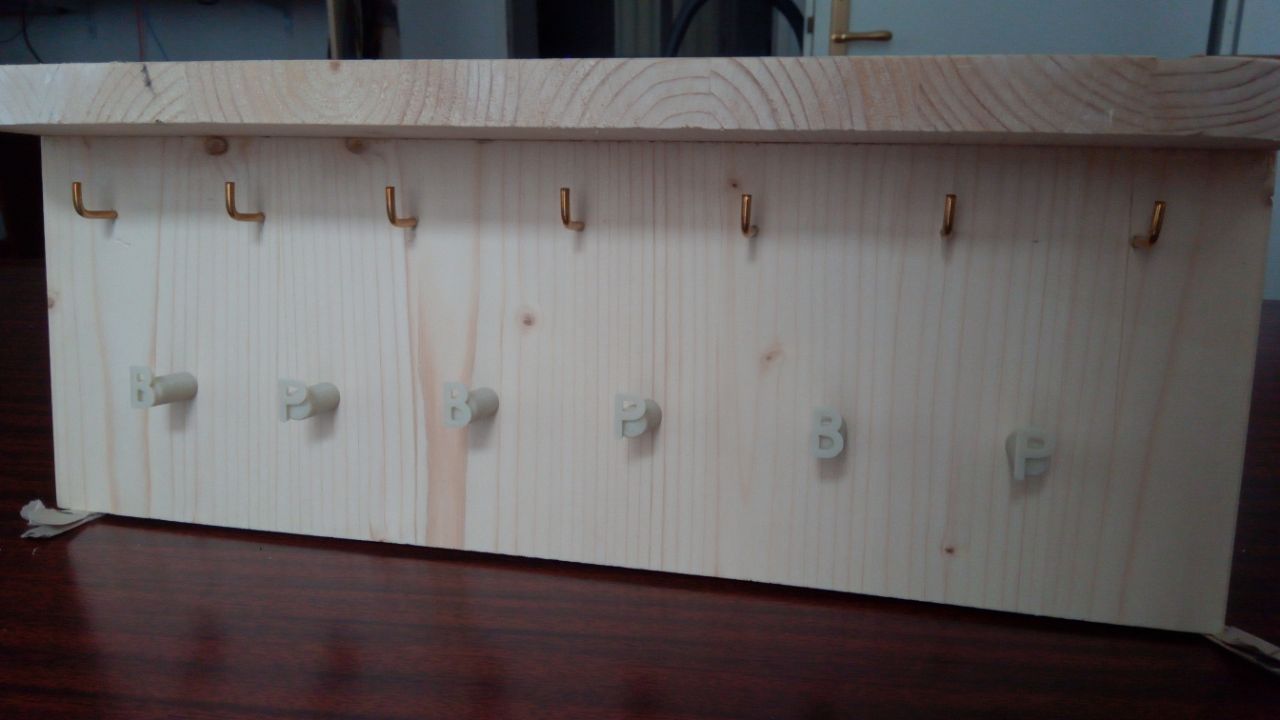
We've never had a key holder tableau, so our keys were just flying around in different places. After making a wall mounted key rack, I had the idea to print custom knobs with glow in the dark filament so we can find stuff in the dark too.
All project parts and additional photos are on github.
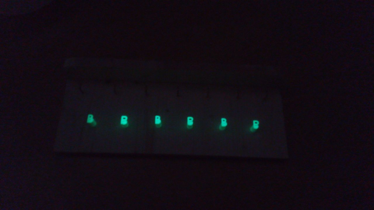
Photo of our the key rack in the dark
Parts
The parts were drawn in solidworks and can be opened in a more or less recent version. The filament is from colorfabb.com and just standard PLA with phosphorescent pigment. They have a hole in the back in order to accommodate a 4x30mm SPAX screwed in from the back through the wood.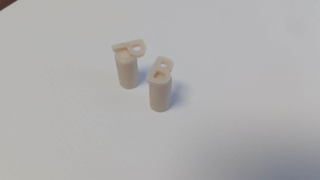
The knobs
Shelf
This is just a gimmick, but the rack had to have a small shelf were we can add more stuff that doesn't come with holes. It perfectly fits a pack of tissues.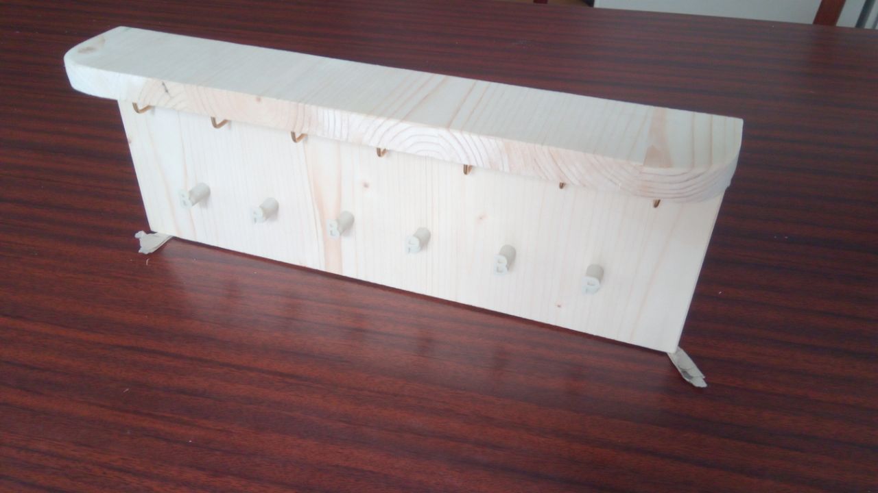
Shelf display
Showcase
In the end it looks quite nice, even during the day. Everything looks reasonably matching, would print again ;)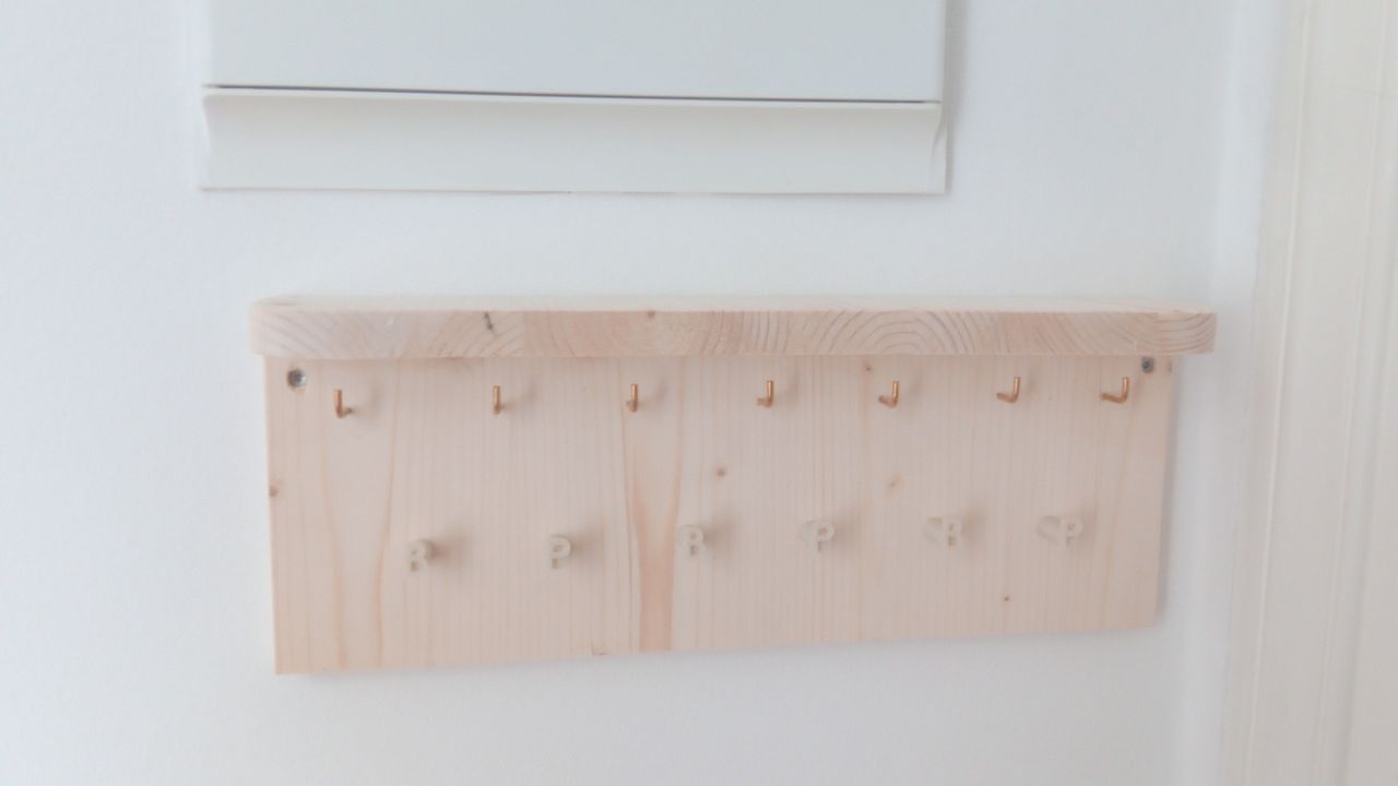
Everything screwed to the wall
If you're interested in this project, take a look at the git or just write a message or leave a comment. Read More
Egg mill - egg shell grinder
by QC
Posted on Sun, May 03, 2020 - 03:56:41 PM
Motivation
A while ago we've started an indoor compost in our flat. This so called 'worm box' is filled with earthworms and other helpful organisms. Those break down our leftover vegetables and give us ultra healthy humus and fertilizer for our plants. Every now and then the box need some minerals for the worms to grow big and strong and to avoid flies to grow. This mineral mix can be bought, but also home made out of dried egg shells. The shells accumulate almost on their own, just grinding them down with mortar and pestle is quite a time consuming task. A couple of days ago we've gotten our hands on a broken coffee machine with integrated grinder and the solution was born.
All project parts and additional photos are on github.
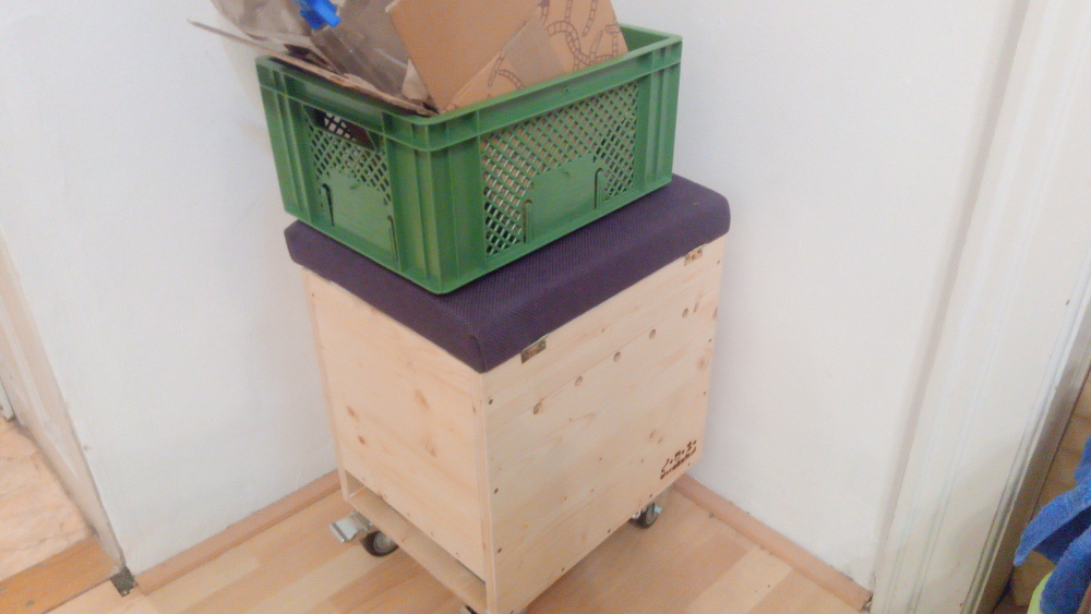
Photo of our worm box
Grinder donor
 The coffee maker had some repair done and after trying to fix it one last time just decided to die. Before throwing it away though, the grinder was saved, still in mint condition. It is driven by a 230VDC (DC!) motor, therefore a little circuitry for rectification and voltage adaption was on the original PCB. I took off the parts needed and threw them on a PCB, the schematics are down below. If you want to reproduce this project and think you have a similar machine, you should be fine with little to no adaptions. The machine was a "Saeco Intuita" for reference. Please note that the 230VAC can be lethal and you have to take great care. I don't take any responsibility whatsoever if you build this yourself.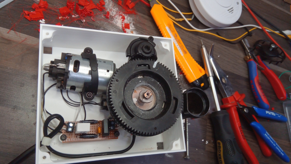
The grinder and circuitry
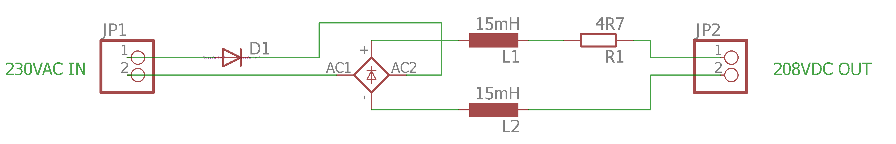
Schematics for rectification and voltage dropping
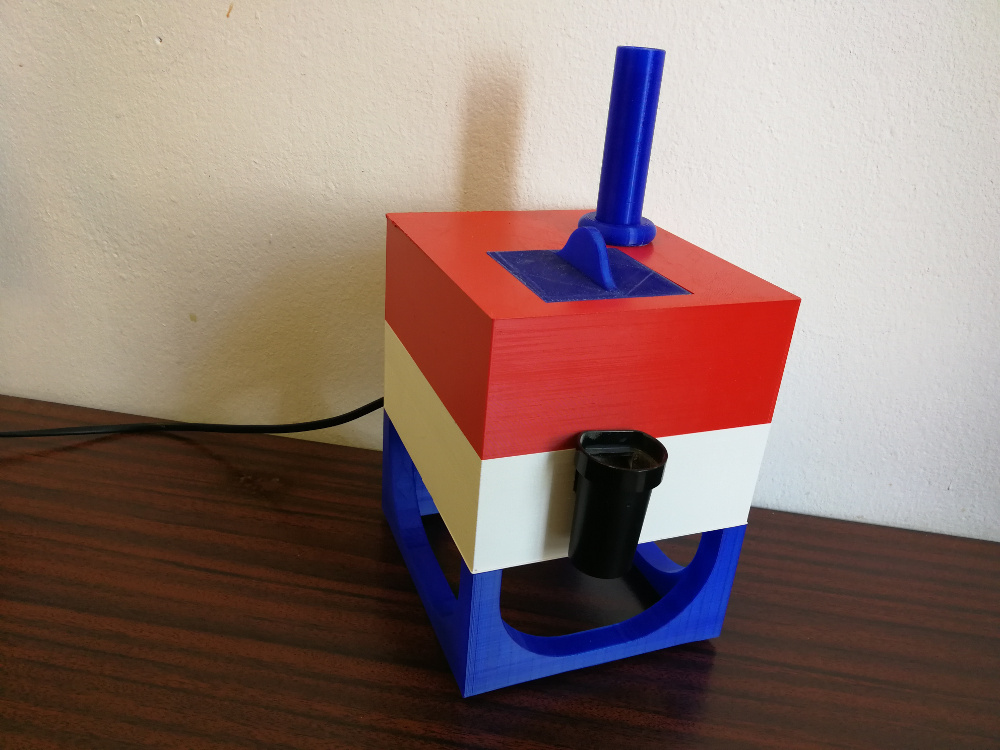
Case
To be able to actually use this mill in a useful way, a case and some extra parts had to be printed. The parts were drawn in solidworks, according to some rough measurements we took beforehands. stl, gcode and other stuff are in the repository.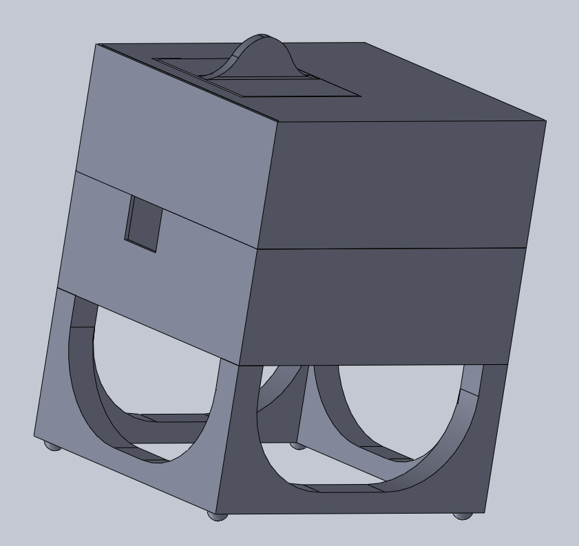
Rendering of the case
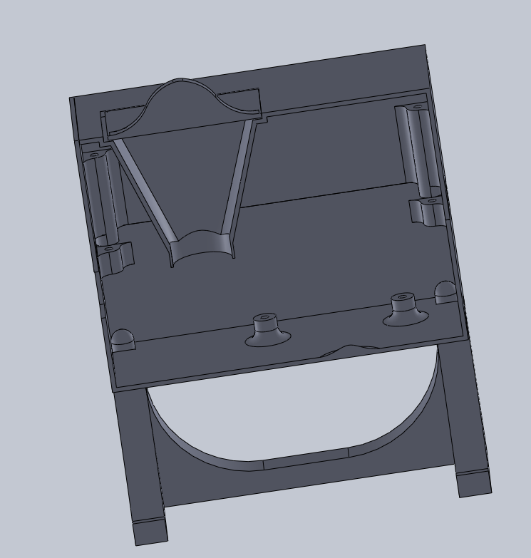
Cut through the case
Result
In the end we printed a lid for dust protection and a small plunger to save our fingers. There's also a small video of it in action and some more photos which i will leave below.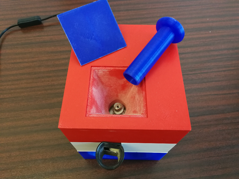
View from the top into the mill
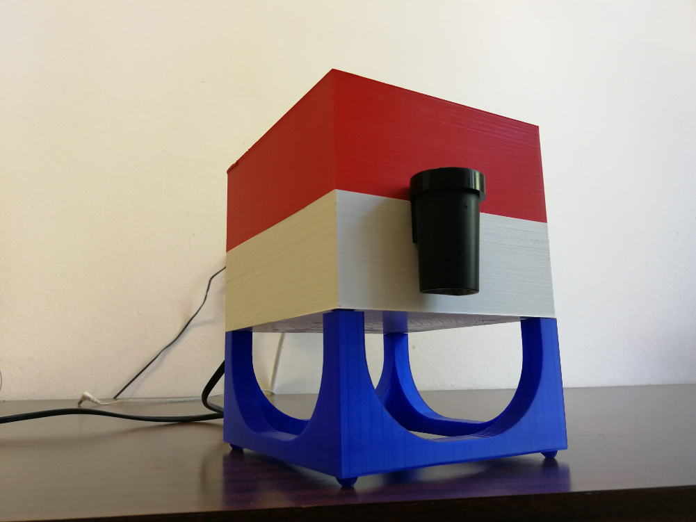
View from below
Video of the mill in operation
433MHz RF modules audio transmission
by QC
Posted on Sat, May 02, 2020 - 01:24:43 AM
Motivation
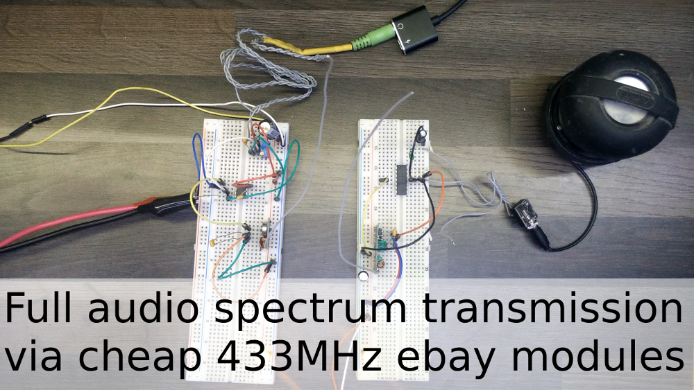
ÂThe other day I've watched a video from great scott, in which he is talking about transmitting audio over cheap 433MHz modules: https://www.youtube.com/watch?v=PKowvbnIxso
He comes to the conclusion that the highest possible frequency for his PWM is ~5kHz, which sounded not reallly plausible to me. Therefore I've ordered such modules off ebay and set them up on my own:
Screenshot of the video.
Video
         ÂTo document this process, I've uploaded a video explaining myself to youtube: https://youtu.be/wH0-SI4t4D0
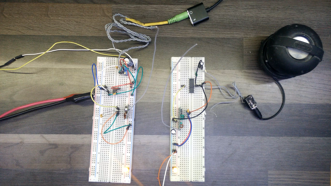
Schematics
The schematics for this project are actually quite simple. It basically decouples and shifts the audio input, mixes it with a triangle wave to get a PWM and then transmits this. The receiver side uses an buffer amplifier for driving an LC filter which filters some of the unwanted noise, before hooking it to the 3.5mm jack: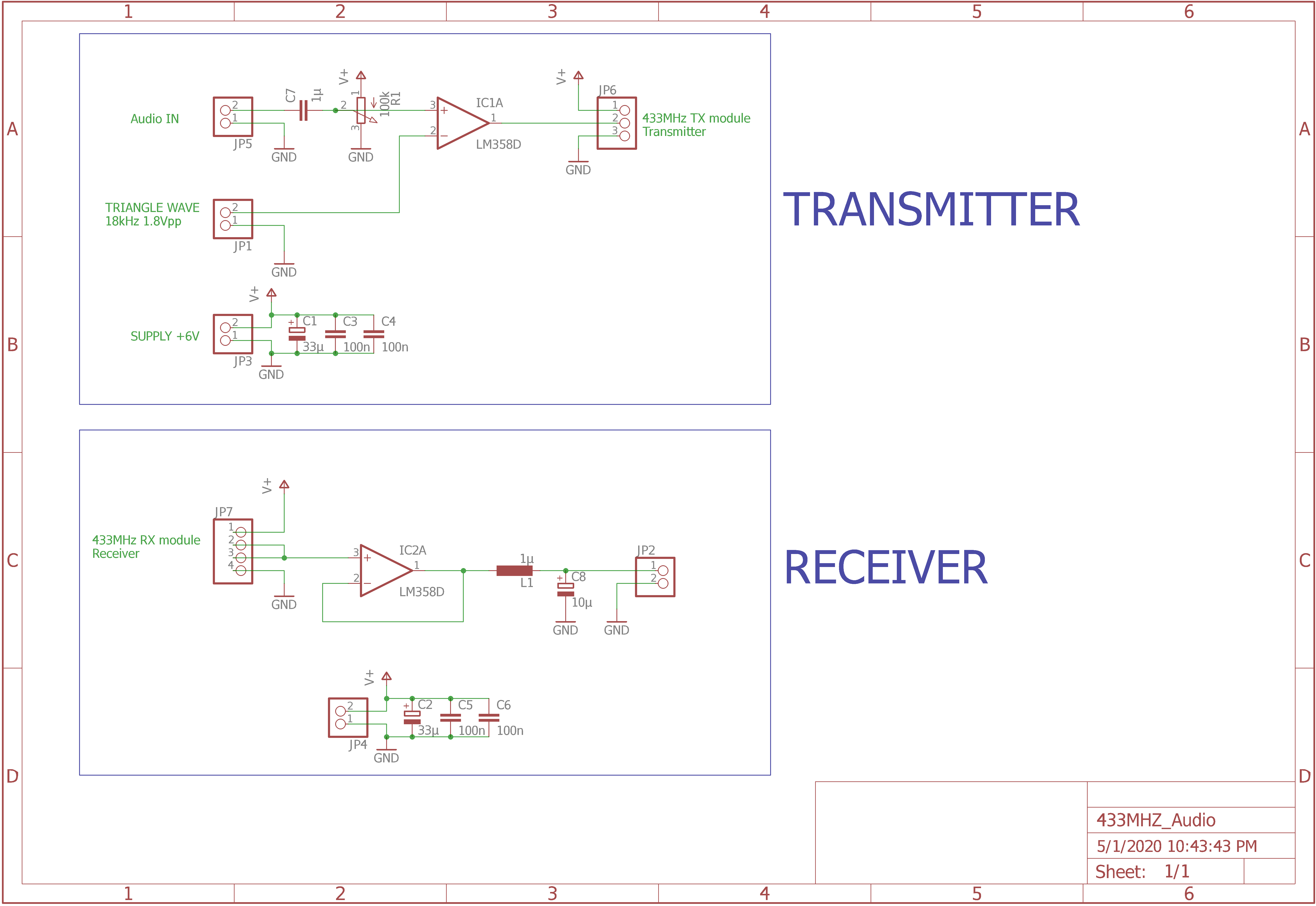
Schematics.
Sound
There is a sound test in the video, but if there is interest, I can record and upload a test file on how good you can work with this, just write me a short message or leave a comment below. Read More3D printed case for a Raspberry Pi with a 5 inch touch screen
by QC
Posted on Mon, April 13, 2020 - 09:34:38 PM
Motivation
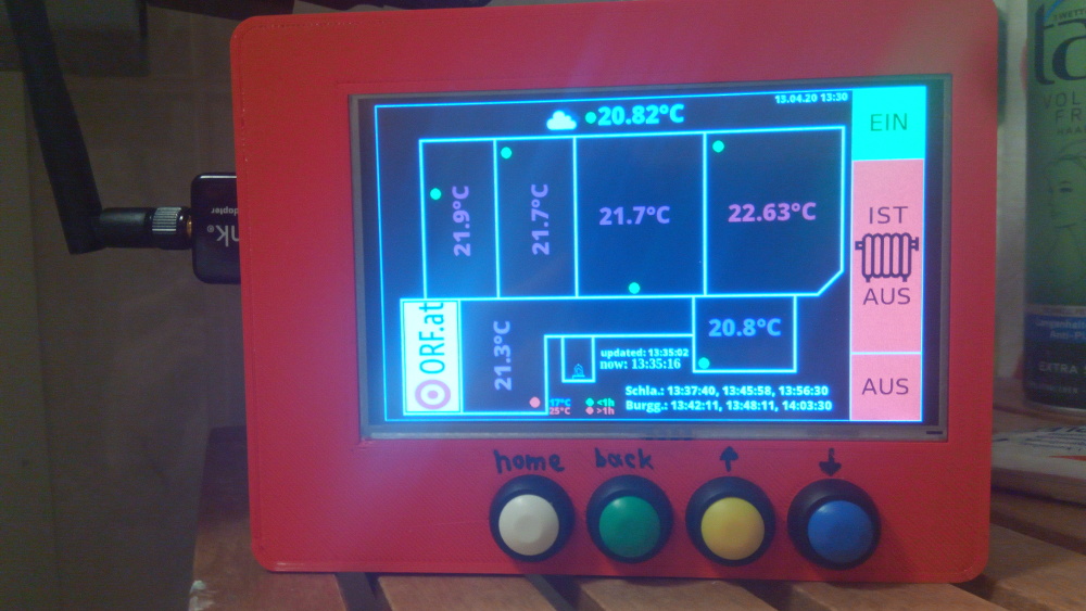
Like many others our flat has quite an interesting bit of home automation. To be able to get a quick overview I made a webpage which shows weather, central heating status, a public transport monitor and has some links to a news website:
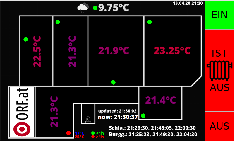
Screenshot of the tool.
3D printed parts
The parts are drawn in solid edge and exported as .stl. They and all the other files, code, photos,... can be found in the github repository. You can slice them yourself and take a look at my design skills or change the .par source files to fit your needs.The four screws are meant to be M3 x 20, if you don't have those just use any reasonably sized ones. They are responsible for holding in the LCD by applying pressure to the back of the raspberry, I've applied some sticky foam tape on the back cover so the Pi can't wiggle around, but without should also be fine.
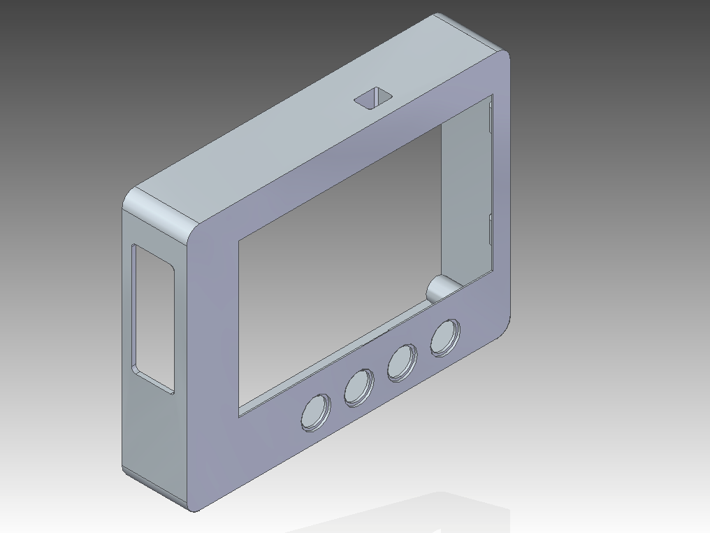
Rendering of the case front
The LCD it quite a perfect fit if printed on my lulzbot mini, maybe you have to play around a bit with the settings. All the other openings should have some room for error, the micro USB has an internal guide so you can plug it in without having to look.
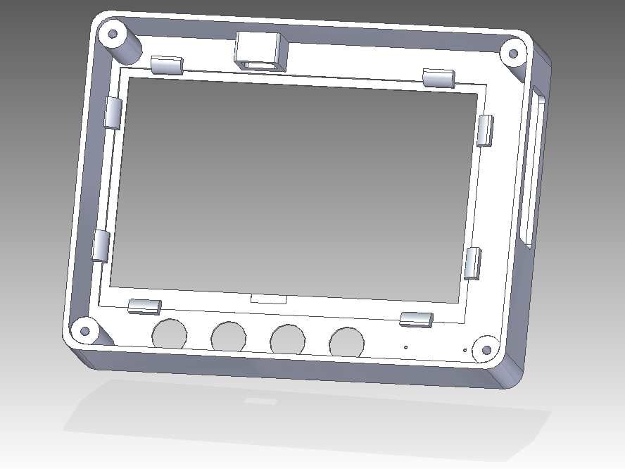
Rendering of the case back
Hardware
I've used a Raspberry Pi 2, but a Pi 3 or 4 should also work. The Display can be pushed directly onto the RPi pins for power and a small HMDI connector was supplied with it. Please make sure to order the right one (HDMI<->HDMI or HDMI<->micro HDMI)The LC-Display is a 5 inch resistive touchscreen, which can be bought for around 25$ from ebay, amazon or any other local electronics store.
The fours buttons are 12mm types, ebay also is your friend here, but any electronic component supplier has those.
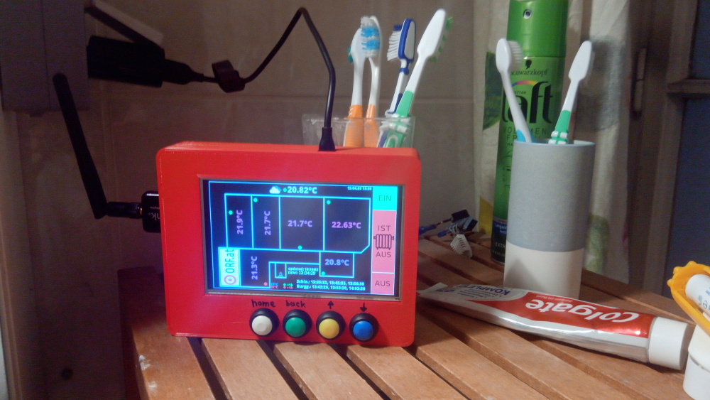
Photo of the unit in its natural habitat
Software
All the code I wrote obviously also is in the github repository, just go from there if you want to do this yourself.The touchscreen should work more or less natively out of the box. If it doesn't or you're unsure about how to setup up your pi, use this instructables.com tutorial. It starts right at the beginning with formatting your SD card and should bring you up to spec with actually inputting stuff over the touch screen.
I've written three files which are important for the function:
- buttonWatch.py: This is a small Python script used to detect pressed buttons and translate them into virtual keyboard presses. Those are in order to operate the chromium / chrome webbrowser which hosts the infoscreen page. The script can 'scroll down', 'scroll up' , 'go to homepage' and 'go back'. The buttons are mapped to four free pins (6,13,19,26) on the RPi header, which are not used by the LCD. You need to install pynput which emulates a keyboard with:
> pip install pynput - startChromium.sh: Starts the buttonWatch.py and then chromium browser in Kiosk mode. It disables the mouse pointer and a few things so it looks nice while idling. Chromium is used for its flexibility and native kiosk mode. The autoupdate has to be disabled and your desired home page has to be set as homepage.
- autostart: this file is the windowmanager (LXDE) autostart procedure and should be copied to .config/lxsession/LXDE-pi/autostart in order for it to be executed when the pi has finished booting up. It basically starts the wifi (only necessary on the Pi2) and then the chromium browser startup script.
Conclusion
I hope this tutorial has helped you or at least gave you an idea on how to make something like this yourself. In case you have any questions, just leave a comment or write me a mail to iq.quiescentcurrentgmail.com.All the best,
QC Read More